22 • PerformanceAlert Gateway I&O Manual
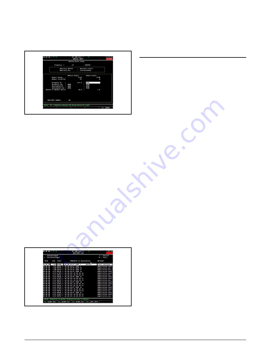
When finished, the Analog Alarm Setup screen should
appear similar to
. Press
J
to save changes
and exit to the Input Status screen.
8.1.3. Advisory Values and Priorities
When setting up Generic Alarming, you will want to
choose advisory types and advisory priorities that are ap-
propriate to the overall alarm filtering and reporting set-
tings for the E2. When alarm dial-outs or annunciation
devices are being used, the E2 will generally be set up to
filter out low-priority alarms and notices. Refer to the E2
User’s Guide for more information about alarm reporting
and dial-out settings.
8.1.4. How the Alarm Appears in the E2
Advisory Log
Because Generic Alarming is not designed specific to
PerformanceAlert™ Gateway, the alarm message generat-
ed when a PerformanceAlert™ alarm occurs will not spe-
cifically say anything about PerformanceAlert™. Digital
alarm messages will read "State Switched ’ON’", and ana-
log alarm messages will read "Occupied Hi Limit Exceed-
ed." The only indicator of which PerformanceAlert™
module generated the alarm will be from the point name
you entered during point setup, which will be shown in the
alarm’s "Property or Board/Point" column in the alarm log
.
In the example in
, since point #1 of the Per-
formanceAlert™ gateway was named "PF COMP 1" when
the point was set up in
, the origin of the
alarm can be seen in the application name.
8.2.
Using PerformanceAlert™
Current Transducer Values
as Compressor Proofs
When the PerformanceAlert™ Gateway is used in Ex-
panded Mode, the T1 and T3 compressor current values
passed in points 13 and 14 of each virtual 16AI board can
be used to verify a compressor is running when command-
ed to run and OFF when commanded to be OFF.
For each compressor with a PerformanceAlert™ mod-
ule installed, one Sensor Control application must be creat-
ed and programmed to read the current values from the
PerformanceAlert™ Gateway and turn an output ON or
OFF depending on whether the current values signify the
compressor is ON or OFF. This Sensor Control output will
be used as the compressor proof and tied to the appropriate
Suction Group compressor proof input.
8.2.1. Creating Analog Sensor Control
Applications
1. Log in to the E2 and press
I
(Add
Application).
2. In the "Type" field, select "Analog Sensor
Control." In the "How many?" field, enter the
number of compressor proofs you will be cre-
ating.
3. Press
>
. The applications will be created.
Press
*
when E2 asks if you want to edit
new applications.
4. Press
H
to return to the home screen.
8.2.2. Programming Analog Sensor
Control Applications
5. Press
I
(Configured Applications).
6. Press
to select "Sensor Controls" from the
Configured Applications menu.
7. From the Sensor Control summary screen,
highlight the name of the analog sensor con-
trol you wish to edit, and press
>
. The
Sensor Control’s Status Screen will be
shown.
8. Press
E
(Setup) to begin editing.
Figure 8-4
- Analog Alarm Setup Parameters
Figure 8-5
- Example of Advisory Log with "State switched On"
Advisory


