background image

20 • PerformanceAlert Gateway I&O Manual

026-1724 Rev 0 12-MAY-2008

8

E2 Applications

The PerformanceAlert™ Gateway provides a means 

for E2 to use data from the PerformanceAlert™ modules 

for general logging, alarming, and control purposes. For 
convenience, this section will cover some of the most com-

mon and useful applications of PerformanceAlert™ data in 

E2 applications.

8.1.

Passing Perfor-
manceAlert™ Alarm Data to 
the E2 Advisory Log

The E2 features many advanced alarm control capabil-

ities, all of which are centered around the collection of 

alarms kept in the E2 Advisory Log. Though the Perfor-
manceAlert™ Gateway passes alarm information from 

PerformanceAlert™ modules to the E2, it only does so as 

I/O point data, not as alarms written to the E2 Advisory 
Log.

In order to write PerformanceAlert™ alarm data to the 

E2 Advisory Log, you must set up Generic Alarming pa-
rameters on the Gateway’s virtual I/O points.

8.1.1. Generic Alarming Setup

Setting up Generic Alarming for PerformanceAlert™ 

Gateway I/O points is done from the E2 Input Status 

Screen.

1. Log in to the E2 and press 

I

 (Input 

Definitions).

2. If you have not yet done point setup for the 

Gateway’s virtual I/O points, follow the steps 
outlined in 

Section 6.2.1., 

Condensed Mode 

Point Setup

  or 

Section 6.3.1., 

Expanded 

Mode Point Setup

. When point setup is com-

plete for all PerformanceAlert™ Gateway 

virtual I/O points, you should see the letter 

"D" next to each PerformanceAlert™ input 
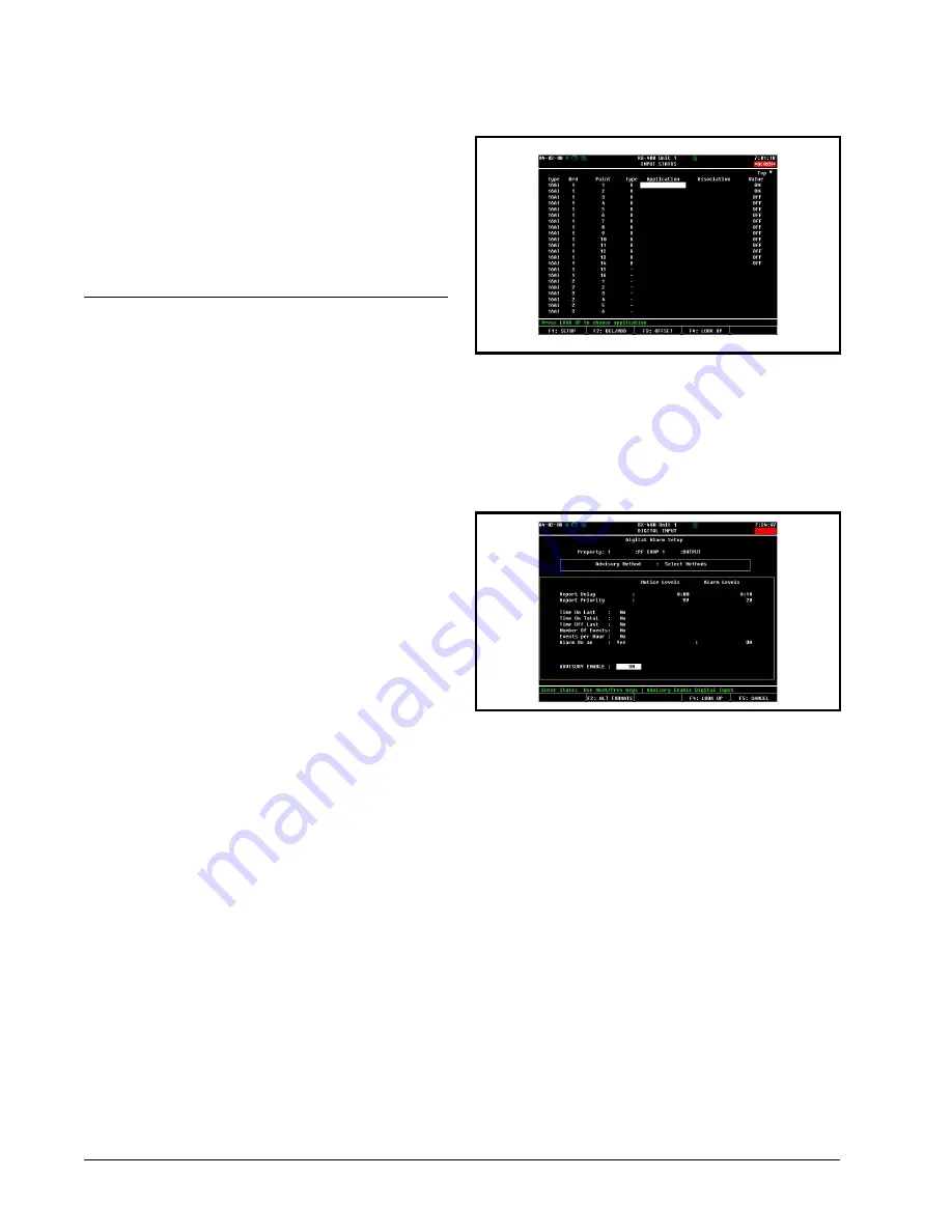
point. In the example 

(Figure 8-1)

, the Gate-

way is operating in Condensed Mode desig-

nated as 16AI board #1, with all fourteen I/O 

points set up:

3. Highlight the point you want to set up. Press 

A

: SETUP. The Digital Input or Analog 

Input screen will be displayed.

4. Press 

A

: SET ALARMS. The Digital 

Alarm Setup or Analog Alarm Setup screen 
will appear.

After completing Step 4, complete generic alarm setup 

by following the instructions appropriate for the input type 
(Digital or Analog).

8.1.2. Alarm Parameter Settings

8.1.2.1. Digital Alarms

For all Condensed Mode data points, and for all Ex-

panded Mode data points except 13, 14, and 15, digital 

alarming may be set up so that an alarm will be generated 

when the point transitions to the ON state.

Continuing from step 4 of 

Section 8.1.1., 

Generic 

Alarming Setup

:

5. Set the Advisory Method field to "Select 

Methods."

6. In the "Alarm On an" field, set this field to 

"Yes" and press 

>

. A field will appear to 

the right of the cursor where you may choose 

which digital state will trigger the alarm. Set 
this field to ON.

Figure 8-1

 - Input Status Screen (Condensed Mode Shown)

Figure 8-2

 - Digital Alarm Setup Screen

Summary of Contents for Copeland PerformanceAlert

Page 1: ...026 1724 Rev 0 12 MAY 2008 Copeland PerformanceAlert Gateway System Installation and Operation Manual ...

Page 2: ......

Page 3: ...accuracies that may be contained herein In no event will Computer Process Controls Inc be liable for any direct indirect special incidental or consequential damages resulting from any defect or omission in this manual even if advised of the possibility of such damages In the interest of continued product development Computer Process Controls Inc reserves the right to make improvements to this manu...

Page 4: ......

Page 5: ...ay Address Switch 7 4 2 2 Setting the Baud Rate Dip Switches 7 4 2 3 Gateway Board RS485 I O Termination 8 5 GATEWAY SOFTWARE SETUP 9 6 PERFORMANCEALERT I O SUMMARY 10 6 1 E2 I O BOARD SETUP 10 6 2 I O SETUP FOR CONDENSED MODE 10 6 2 1 Condensed Mode Point Setup 10 6 3 I O SETUP FOR EXPANDED MODE 11 6 3 1 Expanded Mode Point Setup 11 7 OPERATION 14 7 1 PERFORMANCEALERT STAT SUMMARY 14 7 1 1 Screen...

Page 6: ...sets 19 7 2 5 1 Clear History Log 19 7 2 5 2 Reset PerformanceAlert Module 19 8 E2 APPLICATIONS 20 8 1 PASSING PERFORMANCEALERT ALARM DATA TO THE E2 ADVISORY LOG 20 8 1 1 Generic Alarming Setup 20 8 1 2 Alarm Parameter Settings 20 8 1 2 1 Digital Alarms 20 8 1 2 2 Analog Alarms 21 8 1 3 Advisory Values and Priorities 22 8 1 4 How the Alarm Appears in the E2 Advisory Log 22 8 2 USING PERFORMANCEALE...

Page 7: ... Gateway Figure 1 2 allows you to connect up to fourteen 14 PerformanceAlert Di agnostic Modules On the I O network the Gateway board mimics the behavior of one or more 16AI boards which use virtual 16AI board point addresses to pass along infor mation from the modules to the E2 The PerformanceAlert Gateway is capable of operat ing in one of two different modes a Condensed Mode which maps a single...

Page 8: ... visit www EmersonCli mate com or contact Emerson Climate Technologies Inc at 1 888 EMR 9950 1 4 Hand Held Terminal The Hand Held Terminal HHT P N 811 3110 shown in Figure 1 3 connects directly to the RJ11 jack on the Gateway and is used to configure and view status for the Gateway and its associated modules Copeland P N Application 943 0059 00 1 phase Scroll 943 0057 00 3 phase Scroll 943 0053 00...

Page 9: ...s in Figure 2 1 for panel mounting The Gateway should be mounted in an environment with ambient temperature between 40 F and 150 F with a non condensing relative humidity between 5 and 95 Gateway boards are not supplied with an enclosure but come with a snap track for easy installation The insulation sheet and I O board must be removed from the track before the track is mounted The snap track is m...

Page 10: ...systems Refer to your controller s user manual for information on how to use the center tapped transformers listed in Ta ble 3 1 to power multiple RS485 I O devices for the US and Canada Figure 3 1 shows how to connect the 56VA and 80VA transformers to the Gateway power connector Input Voltage 24VAC Class 2 50 60Hz Power 5VA Table 3 1 Gateway Power Requirements Three Board Six Board P N 640 0056 6...

Page 11: ...ices Figure 4 1 shows two diagrams of valid daisy chain net work structures one with the Gateway at the beginning of the network segment and one with the Gateway in the mid dle of a network segment 4 1 1 PerformanceAlert Module MODBUS Wiring The MODBUS connector for the PerformanceAlert module is located as shown in Figure 4 2 Connect the MODBUS network cable segment s so that the BLACK wire conne...

Page 12: ...minals 4 1 4 MODBUS Termination To minimize network interference on the MODBUS network the daisy chain must be terminated at both end points with all devices in between left unterminated Refer to the diagram in Figure 4 1 for diagrams showing the dai sy chain endpoints The PerformanceAlert module is terminated by plac ing a jumper across the TRMNTR pins The Gateway board is terminated by setting t...

Page 13: ...rough 8 The address DIP switches have no function when the Gate way is set to Expanded mode 4 2 1 1 Setting the Gateway Address Switch If using the PerformanceAlert Gateway in Con densed Mode set the address DIP switches to the virtual 16AI board address you wish the Gateway to use Figure 4 7 The Gateway in Condensed mode behaves in the same manner as one 16AI board whose address is equal to the a...

Page 14: ...daisy chain set the three jumpers next to the I O Network connector to the TERMINATION posi tion as shown in Figure 4 9 Figure 4 8 Dip Switch Setting for Numbering Gateway Figure 4 9 Gateway RS485 I O Network Termination GATEWAY DIP SWITCH I O NETWORK OR COM A AND D BAUD RATE I O NET BAUD RATE SETTINGS 2 3 4 5 6 7 8 1 9600 19200 MODBUS BAUD RATE MODBUS BAUD RATE SETTINGS 9600 ...

Page 15: ...and repeat until all are set correctly IMPORTANT Always set unused ad dresses to DIS In Expanded Mode this will allow the 16AI board number to be used by other I O network devices see Section 6 3 I O Setup for Expanded Mode 5 To move to the next screen press DOWN ARROW until the cursor moves off the bot tom of the HHT screen then press DOWN ARROW one more time The next screen showing PF ALERT 5 th...

Page 16: ...this virtual board correspond to the overall alarm status of PerformanceAlert modules 1 through 14 The point will be ON as long as one or more of the following failure conditions are active 1 The PerformanceAlert module is not com municating with the Gateway OR 2 Alert code 4 5 6 7 8 and or 10 are active OR 3 The compressor is in lockout 6 2 1 Condensed Mode Point Setup To set up the Gateway s vir...

Page 17: ...the corresponding alarm type is active on the PerformanceAlert module and OFF when the alarm type is not active Point 12 represents the digital state of the Perfor manceAlert s compressor relay ON when the compres sor relay is ON and OFF when the compressor is OFF Points 13 and 14 are the measured currents through T1 and T3 respectively Point 15 is the measured temperature read from the dis charge...

Page 18: ...lect Eng Units field press F4 to ac cess the Look UP table Highlight A as the unit type and press to select 7 The Low Eng Units and High Eng Units fields near the bottom of the screen must be set to 0 and 655 5 respectively The Low Eng Units by default should read 0 and will not re quire modification Move the cursor to the High Eng Units field and enter 655 5 as the new value 8 Press J to save the...

Page 19: ... for Expanded Mode PerformanceAlert I O Summary 13 you may set up logging alarming and if desired output control Refer to the E2 User s Guide P N 026 1610 for Analog and Digital Sensor Control setup instructions ...

Page 20: ... select STAT SUMMARY Press the DOWN AR ROW key two times to navigate to the first stat summary screen The six screens under the Stat Summary heading will show you online status alarm status and firmware version for the PerformanceAlert modules 7 1 1 Screen 1 Comm Status Comm Status The list of characters on Line 3 of the HHT display which are numbered 1 through 14 by the numbers above them on Line...

Page 21: ... view Press DOWN ARROW twice You may only select a PerformanceAlert address for a module that is set to ENABLE and is communicating with the Gateway If a module is not enabled or is not com municating an error message will be given If the address selected is on line the Individual Module Menu will be shown 7 2 1 Individual Module Status To view the status screens press RIGHT ARROW to move the curs...

Page 22: ...3 through 11 show the 7 day history of each of the alarm codes from 1 through 9 showing which days they have occurred The current day which represents the pe riod of time between the current time and 24 hours ago is displayed under the C The remaining seven fields repre sent alarm occurrences from 1 to 7 days previous to the cur rent time If one or more alarms have occurred during any of the days ...

Page 23: ...played un der the C The remaining seven fields represent alarm oc currences from 1 to 7 days previous to the current time If one or more trips or bypasses have occurred during any of the days displayed on this screen a Y will appear un der the day the trip s or bypass es occurred Otherwise an N will be shown meaning no trips or bypasses occurred on that day The Count field at the bottom of each sc...

Page 24: ...the DLT TTP setpoint in degrees Farrenheit a HIGH DISCHARGE alert will oc cur The Severe Alert OFF Time is the minimum number of minutes the compressor will remain OFF when a trip oc curs as a result of an alarm code 1 4 6 or 7 When one of these alarm codes occurs the compressor will not reset un til the Severe Alert OFF Time delay has elapsed The LO V STP is the setpoint for low voltage trip An v...

Page 25: ...his screen press the CANCEL key The MSG SNT NO RESP BAD CRC INVALID and MX counts will all reset to zero 7 2 5 Resets From the Reset menu option you may clear a Perfor manceAlert module s history log or reset the module it self From the Individual Menu select 5 to view the Reset Menu 7 2 5 1 Clear History Log Performing a Clear History operation will erase all history statistics for the selected P...

Page 26: ... the steps outlined in Section 6 2 1 Condensed Mode Point Setup or Section 6 3 1 Expanded Mode Point Setup When point setup is com plete for all PerformanceAlert Gateway virtual I O points you should see the letter D next to each PerformanceAlert input point In the example Figure 8 1 the Gate way is operating in Condensed Mode desig nated as 16AI board 1 with all fourteen I O points set up 3 Highl...

Page 27: ...that represents a PerformanceAlert module when the Gateway is operating in Expanded Mode Points 13 and 14 are current values point 15 is the discharge line temper ature Of these analog points it is not necessary to set up ge neric alarming on points 13 and 14 On point 15 the dis charge line temperature alarming already occurs with high discharge causes a trip condition to occur in Expanded Mode Ge...

Page 28: ...m can be seen in the application name 8 2 Using PerformanceAlert Current Transducer Values as Compressor Proofs When the PerformanceAlert Gateway is used in Ex panded Mode the T1 and T3 compressor current values passed in points 13 and 14 of each virtual 16AI board can be used to verify a compressor is running when command ed to run and OFF when commanded to be OFF For each compressor with a Perfo...

Page 29: ...3 amps and OFF whenever it falls below 2 5 amps Leave the Cut In Delay and Cut Out Delay fields set to 0 00 00 8 2 3 Setting Up Proofing in Suction Group Applications After entering the CUTIN and CUTOUT setpoints in the Setpoints tab Section 8 2 2 3 press to save changes and exit You are now ready to configure the compressor in the suction group to use the output of the sensor control ap plication...

Page 30: ...C to change the definition type from a Board Point to a Controller Application Output type definition 9 For each field in the Controller Application Output use the Look Up Table D to point the COMP PROOF input to the output of the Analog Sensor Control application CONTROLLER Name of this E2 APPLICATION Choose the name CMPR x PROOF you entered for the Analog Sensor Con trol application OUTPUT Choos...

Reviews: