Emerson Research X-STREAM Series Instruction Manual Addendum Download Page 64

Emerson Process Management GmbH & Co. OHG

2-22

X-STREAM XEFD

Instruction Manual

HASXEDE-IM-EX

07/2017

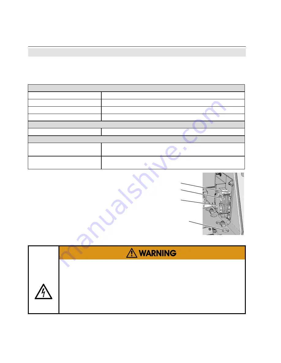
Connecting the power cord

To install the cable proceed according to the 

installation instructions for either conduits or 

cable glands, given by the manufacturer.

Insert the power cord through the foremost 

entry, strip the outer insulation, skin and 

connect the conductors to the terminals (a 

descriptive label is attached nearby the termi

-

nals), by inserting them from the bottom sides.

2.5   Installation – Electrical

The power cord is connected to screw-type terminals located inside the housing.


ELECTRICAL SHOCK HAZARD

Verify that the power supply at installation site meets the specification given 

on the analyzer’s nameplate label, before installing the instrument!
Verify power cables are disconnected and/or instrument is de-energized 

prior to working at the terminals!
Verify the power cord is layed with a distance of at least 1 cm (0.5") to any 

signal cable to ensure proper insulation from signal circuits!

Electrical Connections

Power terminals

screw terminal with integrated fuse holders max 4 mm² 

Supported wire cross sections 0.2 to 4 mm

2

 (24 to 12 AWG) no need to use wire end sleeves

Cable skinning length

8 mm (0.315 inch);  

Tightening torque, min .

0.5 Nm (4.4 in.lb)

Power Inlet Fuses

Data

AC 230 V  /  T 4 A  /  5x20 mm

Cable Inlets

Variations

approved, M20 x 1,5, Cable glandes, min. IP 66, or 


conduits with adaptors (metric-2-NPT)

Outer cable diameter 


(cable glands)

depending on cable gland

Power cord entry

L= Line

N=Neutral

PE=Protective Earth

Fig. 2-16: 

Power terminals

L

PE

N

Summary of Contents for X-STREAM Series

Page 1: ...w emerson com Instruction Manual HASXEDE IM EX 07 2017 Gas Analyzer X STREAM Enhanced Series Flameproof Variation For Use in Zone 1 and Division 2 Hazardous Areas Instruction Manual Addendum 10th Edition ...

Page 2: ...nd maintenance of the product Install your equipment as specified in the Installation Instructions of the appropriate Instruction Manual and per applicable local and national codes Connect all products to the proper electrical and pressure sources To ensure proper performance use qualified personnel to install operate update program and maintain the product When replacement parts are required ensu...

Page 3: ... Use S 7 Chapter 1 Technical Description 1 1 1 1 Overview 1 1 1 2 Design Features 1 1 1 3 Protective Measures in Detail 1 2 1 4 High Pressure Option Purge Option 1 3 1 5 Explosion Protection Compliances 1 4 1 5 1 Special Conditions for Safe Use 1 5 1 6 Nameplate Label Examples 1 6 1 7 Technical Data 1 7 1 8 Measurements Specifications 1 15 1 9 Vapor Recovery Application Simultaneous Measurement of...

Page 4: ...ecking the Settings 3 15 3 9 1 Installed Options 3 16 3 9 2 Configuring the Display 3 17 3 9 3 Calibration Setup 3 18 3 9 4 Setting the Analog Outputs 3 20 3 9 5 Setting Concentration Alarms 3 25 3 9 6 Backup the Settings 3 26 3 10 Web Browser 3 28 3 10 1 Connection via network 3 28 3 10 2 Connection to single computer 3 29 3 11 Start the measurement 3 31 Chapter 4 Service and Maintenance 4 1 4 1 ...

Page 5: ...minals 1 13 Fig 1 7 Power Terminals Fuse Holders 1 14 Fig 1 8 Vapor Recovery Gas Flow Diagram 1 20 Fig 2 1 Scope of Supply 2 1 Fig 2 2 Dimensions 2 3 Fig 2 4 Installation in bypass mode 2 7 Fig 2 3 Labelling of gas connectors example 2 7 Fig 2 5 Flame arrestor installed into instrument enclosure 2 8 Fig 2 6 Flame arrestor elements considering as example FA 01 2 8 Fig 2 7 Exemplary diagram for a si...

Page 6: ...n setup 4 9 Fig 4 4 Location of Overtemperature Protection Device 4 12 Index of Figures Index of Tables Index of Tables Tab 1 1 Generic Analyzer Data 1 8 Tab 1 2 Standard Interfaces Data 1 9 Tab 1 3 Optional Interfaces Data 1 10 Tab 1 4 Increased Pressure Data 1 12 Tab 1 5 Purging Gas Data 1 12 Tab 1 6 Gas Components and Measuring Ranges examples 1 15 Tab 1 7 IR UV VIS TCD Standard and Enhanced Me...

Page 7: ...a tions and therefore may describe configurations and or options not part of your specific analyzer INTRODUCTION The following definitions apply to WARNINGS CAUTIONS and NOTES found throughout this publication DEFINITIONS NOTE Highlights an essential operating procedure condition or statement HIGHLIGHTS AN OPERATION OR MAINTENANCE PROCEDURE PRACTICE CONDITION STATEMENT ETC If not strictly observed...

Page 8: ... of the analyzer housing Lower Explosion Limit LEL Volume ratio of flammable gas in air below which an explosive gas atmosphere will not be formed the mixture of gas and air lacks sufficient fuel gas to burn Lower Flammable Limit LFL The concentration of flammable gas vapor or mist below which an explosive gas atmo sphere will not be formed when mixed with air Protection Class IP66 NEMA 4X Both te...

Page 9: ...y be accessible Removing covers by qualified personnel is permitted only if the instrument is disconnected from power Nevertheless several surfaces may remain hot for a limited time more detailled information available see in struction manual before proceeding more detailled information available see in struction manual before proceeding Wherever one or more of the following symbols appear on or i...

Page 10: ...al means dangerous voltages may be exposed hot surfaces may be exposed possible danger of explosion toxic substances may be present substances harmful to health may be present indicates notes relating to heavy instruments electrical components may be destroyed by electrostatic discharges units must be disconnected from the power source indicates special instructions or information for operation at...

Page 11: ...t found in air or other oxidizer are outside the scope of the used standards and the X STREAM enhanced flameproof certificate Sample gases are allowed to contain Oxygen only up to 21 Equipment for flammable sample gas can be identified by the ordering code on level 2 OptionsA B and the respective note on the type plate Equipment for non flammable sample gas can be identified by the ordering code o...

Page 12: ...instruction manual depending on what is used Contact your local service center or sales office when missing documents SAVE ALL INSTRUCTIONS FOR FUTURE USE Authorized Personnel In depth specialist knowledge is an absolutely necessary condition for working with and on the analyzer Authorized personnel for installing operating servicing and maintaining the analyzer are instructed and trained qualifie...

Page 13: ...athing device Take special care handling flammable gas at the outlet of breathing and or purging devices if the sample gas concentration is above 25 LEL If need be such outlets habe to end in safe area Vapor recovery application Pressure of gases not to exceed 1100 hPa concen tration of gases must be below 25 LEL Appropriated certified Ex Equipment cable glands shall be used in accordance with EN ...

Page 14: ... OPEN the analyzer enclosure if explosive atmosphere may be present Disregarding may cause explosion even if the analyzer is de energized ELECTRICAL SHOCK HAZARD Installation and connecting mains and signal cables are subject to qualified personnel only taking into account all applicable standards and legislative requirements Failure to follow may cause warranty invalidation property damage and or...

Page 15: ...nterruption of the earth connector inside or outside the instrument or disconnecting the earth terminal may cause potential electrical shock hazard Intended interruption of protective earth connections is not permitted EXPLOSION HAZARD BY DAMAGED FLAME PATHS Take care to not damage the housing nor threads and to not produce scratches on the flange as threads and flange function as flame paths Viol...

Page 16: ...ardous atmosphere is present Depending on the local regulation this may require a competent hot work supervisor to issue a hot work permit Use ALL 20 screws with the respective torque to fix the cover Violation may cause an explosion hazard EXPLOSION HAZARD BY HIGH PRESSURE Risk of internal overpressure under leakage conditions For normal operation up to 1100 hPa 1 45 psig sample gas pressure the ...

Page 17: ... instructions Especially all warnings in this and the associated manuals have to be considered Inspection maintenance and service must be carried out considering all related standards e g for Inspection and maintenance of electrical installations in hazardous areas or Equipment repair overhaul and reclamation EXPLOSION HAZARD VAPOR RECOVERY APPLICATION Consider the waiting time statement on the fr...

Page 18: ...e care to use anchors and bolts specified to be used for the weight of the units Take care the wall or stand the unit is intended to be installed at is solid and stable to hold the units HIGH TEMPERATURES HAZARD While working at internal components hot surfaces may be accessible even after the instrument has been disconnected from power HAZARD TO LIFE AND EXPLOSION HAZARD BY EXHAUST GASES Exhaust ...

Page 19: ...ents in the unit CRUSHING HAZARD Take care of crushing hazard when closing the front door of analyzer field housings Keep out of the closing area between enclosure cover and base OPERATION AT LOW TEMPERATURES When operating an instrument at temperatures below 0 C 32 F do NOT apply gas nor operate the internal pump before the warmup time has elapsed Violation may result in condensation inside the g...

Page 20: ... and according to applicable regulations If it is necessary to disconnect the gas lines the unit s gas connectors must be sealed with PVC caps to avoid polluting the internal gas lines with condensate dust etc To ensure electromagnetic compatibility EMC only shielded cables supplied by us on re quest or of equivalent standard may be used The customer must ensure that the shielding is correctly fit...

Page 21: ... results in high temperatures flames or even an explosion is to keep the explosion inside the enclosure and quench all flames possibly passing through the flange To provide adequate explosion protection the X STREAM flameproof analyzer feature a cast aluminum enclosure designed to withstand an internal explosion quench flames resulting from an internal explosion thus preventing a surround ing expl...

Page 22: ...base Two fitting sizes are available for ex ternal connection of gas pipes with 3 18 mm 1 8 or 6 35 mm 1 4 outer diameter OD Op tionally a clamping ring for 6 mm OD may be used replacing the 6 35 mm version Unused threads are closed with blind plugs which are certified within the Emerson approvals Cables are fed into the enclosure utilizing up to 4 cable glands located at the enclo sure s bottom r...

Page 23: ...oth situations higher sample and calibration gas pres sures as well as purging the housing with a gas for best measuring results at low concentrations To permit this special additional conditions must be taken into account High sample and calibration gas pressures Higher gas pressure is specified to be within the range of 1100 hPa to 1500 hPa The maxi mum permitted flow is 1 5 l min depending on t...

Page 24: ... ISA 12 22 01 2002 IEC 60079 1 Mod Furthermore these X STREAM XEFD ana lyzers are certified for use in Class I Divi sion 2 Group BCD T3 areas See electronic documentation for a copy of the CSA Certificate of Compliance IECEx certification enables worldwide approv als with minimized need of testing Further more based on this approval several national approvals are granted For a comprehensive list o...

Page 25: ...ly of the parts of flame proof enclosure special fasteners with a minimum property class A 70 shall be used The gas path for the sample gas shall be equipped with additional appropriate flame arresters in case of gas pressure above 1100 hPa to 1500 hPa and enclosure has to be equipped with additional breathing device Take special care handling flammable gas at the outlet of breathing and or purgin...

Page 26: ... 4X Enclosure Rating outdoor use Additional Division Marking if appli cable Class I Flammable gases vapors or liquids Division 2 Division 2 areas Groups BCD all Gases except Acetylene T3 Temperature Class 200 C Certificate numbers IECEx FTZU 08 0004X FTZU 08 ATEX 0028 X 1714037X Other CE mark number of Notified Body for Quality assessment Instruction note where to install the explosion proof seal ...

Page 27: ... removed after installation Fig 1 4 Dimensions Housing Permissible operating ambient tem perature range max ATEX IECEx 20 C to 55 C 4 F to 131 F CSA 20 C to 55 C 4 F to 131 F Permissible storing ambient tem perature range 30 C to 70 C 22 F to 158 F Weight approx up to 63 kg 139 lbs depending on analyzer configuration Protection class IP 66 EN 60529 Type 4X for outdoor installation Analyzer must no...

Page 28: ... safety Canada USA CSA C US based on CAN CSA C22 2 No 61010 1 04 UL 61010 1 2nd Edition Europe CE based on EN 61010 1 Electromagnetic compatibility Europe CE based on EN 61326 Australia C Tick others NAMUR Power supply Rated input voltage 100 240 V 50 60 Hz Input voltage range 85 264 V 47 63 Hz Nominal input current standard 1 3 0 7 A with temperature control 3 1 5 A Measurement channels max 5 Gas...

Page 29: ... outputs electrical specification dry contacts max load 30 V 1 A 30 W resistive function Each output can be configured to provide any of the functions listed in chapter 6 of the X STREAM Enhanced instruction manual These functions in clude but are not limited to NAMUR NE 107 status signals Failure Maintenance request Out of specification Function check concentration alarms control signals for exte...

Page 30: ...p Zero calibrate all channels Span calibrate all channels Zero and span calibrate all channels Abort calibration 9 or 18 additional relay outputs electrical specification Dry relay change over contacts can be used as NO or NC max load 30 V 1 A 30 W resistive function Each output can be configured to pro vide any of the functions listed in chap ter 6 of the X STREAM XE instruction manual These func...

Page 31: ...y isolated from analyzer GND protected against overload up to 15 V or 20 mA function Input analog signals from external devic es such as e g pressure transmitters flow sensors analyzers etc for compensation or other purposes 1 Interface electrical specification 9 pin optically isolated from analyzer elec tronics function RS232C RS485 or Modbus 1 Service interface electrical specification RS232C NO...

Page 32: ...red gas concentration is below 25 V V LEL Otherwise it must end in safe area Consider the special conditions for safe use 1 4 and 1 5 1 Purging the housing to reduce cross interference Maximum gas flow 2 l min Permitted purge medium Inert gas or air Dry clean free of corrosives or components contain ing solvents and free of components to be measured Its tempera ture must correspond to the ambient ...

Page 33: ...ockets USB connections Cable glands type threads M20x1 5 6H necessary IP 66 or NEMA 4X Approved for hazardous areas Permissible outer cable diameter see cable gland conduit specification Detailed terminals configuration Chapter 2 Installation Note Depending on the actual analyzer configuration not all shown or different terminals may be provided 1 Ethernet Service port USB 2 Ethernet for network c...

Page 34: ...rotective earth terminal PE 3 Power cable entry 4 EMI power supply filter 3 2 4 1 Power connections Power supply Connection via internal screw terminals near cable en tries max 4mm 10 AWG end sleeves not required Power supply fuses Fuse ratings AC 230 V T 4 A 5x20 mm Cable glands Types M20x1 5 6H necessary IP 66 or NEMA 4X Approved for hazardous areas Permissible outer cable diameter see cable gla...

Page 35: ...m 0 100 Helium He TCD 0 10 0 20 0 100 Hexane 1 C6 H14 IR 0 100 ppm 0 200 ppm 0 10 Hydrogen 4 H2 TCD 0 1 0 2 0 100 Hydrogen Sulfide H2 S UV 0 2 0 4 0 10 Hydrogen Sulfide H2 S IR 0 10 0 20 0 100 Hydrogen Sulfide H2 S electrochem 0 50 ppm 0 2000 ppm 6 Methane CH4 IR 0 100 ppm 0 200 ppm 0 100 Methanol 1 CH3 OH IR 0 1000 ppm 0 2000 ppm 0 10 n Butane C4 H10 IR 0 800 ppm 0 1600 ppm 0 100 Nitrogen dioxide...

Page 36: ...5 per 10 K 1 per 10 K 0 5 per 10 K On span sensitivity 5 0 to 50 C 32 to 122 F 1 per 10 K Thermostat control 6 12 none 60 C 140 F 5 none 60 C 140 F 10 Warm up time 6 15 to 50 minutes 5 approx 50 minutes Note 1 psi 68 95 hPa 1 Related to full scale 2 Related to measuring value 3 From gas analyzer inlet at gas flow of 1 0 l min electronic damping 0 s 4 Constant pressure and temperature 5 Dependent o...

Page 37: ...ump 9 Temperatures below 0 C 4 F with thermostat control only 10 Thermost controlled sensor 35 C 95 F 11 For ranges 0 5 100 and flow 0 5 1 5 l min 12 Optional thermostatically controlled sensor with temperature 60 C 140 F 13 Temperature variation 10 K per hour 14 No sudden pressure surge allowed Oxygen Sensors Paramagnetic pO2 Electrochemical eO2 Trace tO2 Standard Spec Enhanced Spec Detection lim...

Page 38: ...ty drift 1 2 4 2 resp 0 2 ppm 9 Repeatability 1 2 2 resp 0 2 ppm 9 Response time t90 7 10 s Permissible gas flow 0 2 1 5 l min Influence of gas flow 1 2 2 Maximum gas pressure 10 11 1500 hPa abs 7 psig Influence of pressure 5 At constant temperature 0 1 per hPa With pressure compensation 8 0 01 per hPa Permissible ambient temperature 15 to 35 C 59 to 95 F 5 to 40 C 41 to 104 F Influence of tempera...

Page 39: ...permissible ambient temp range Note 1 psi 68 95 hPa 98 100 CO2 Detection limit 4 σ 1 2 2 Linearity 1 2 1 Zero point drift 1 2 3 2 per day Span sensitivity drift 1 2 3 2 per day Repeatability 1 2 2 Response time t90 4 30 s Permissible gas flow in the external sample handling system a very stable flow has to be generated Please C F factory for details Permissible gas pressure Permissible gas pressur...

Page 40: ...tion is only available for ambient temperatures from 20 C to 50 C and for non flammable sample gases Fig 1 8 Vapor Recovery Gas Flow Diagram XWWHU 7 9 H HLFKQHU HVLJQDWRU HQHQQXQJ HVFULSWLRQ LOWHU LOWHU ODPPHQVSHUUHQ ODPH UUHVWRU 7 URVVHO 7KURWWOH 9 9HQWLO 9DOYH FKXW YHUPHUN 1 EHDFKWHQ HUVRQ 3URFHVV 0DQDJHPHQW PEK R 2 2 JDVIORZ GLDJUDP FXWWHU 2 0D VWDE VFDOH HQHQQXQJ HVFULSWLRQ HLFKQXQJ 1U UDZLQJ ...

Page 41: ...ctivating the valve V1 For the ease of use special PLC and calcula tor programs are provided with analyzers for vapor recovery applications automatically calculating the efficiency each time after a calibration has been performed The calcu lated value shows up as a measurement result on the measurement display To calculate the efficiency without a preced ing calibration you can also start the PLC ...

Page 42: ...Emerson Process Management GmbH Co OHG 1 22 X STREAM XEFD Instruction Manual HASXEDE IM EX 07 2017 ...

Page 43: ...ortation because only the original packaging ensures proper protection HAZARDS FROM MISSING INFORMATION Compare the content of your package with the pictures below Analyzers for hazardous areas need additional parts described in the accompanying documentation refering to hazardous area installations Call your local sales office if something is missing and DO NOT continue to install your analyzer u...

Page 44: ...ning the housing and working at open instrument This is permitted only if no hazardous atmosphere is present and the instrument and connected circuitry is deenergized Depending on the local regulation this may require a competent hot work supervisor to issue a hot work permit Use ALL 20 screws with the respective torque given on the label to fix the cover Violation may cause an explosion hazard EX...

Page 45: ...entations may affect the measuring results Fig 2 2 Dimensions Cable inlets enclosure threads M20 x 1 5 Flame arrestors with gas fittings enclosure threads M18 x 1 5 Eyebolt detail All dimensions in mm inches in brackets Transport lugs to be removed after installation EXPLOSION HAZARD When installing the analyzer take care to have an area of min 40 mm 1 6 surrounding the flange free of any solid co...

Page 46: ... e g by corro sion or solvents Pressure and gas flow must remain within the values given in the Measurement Specifications section within this manual If moisture cannot be avoided it is necessary to ensure that the dew point of the gases is at least 10 C 18 F below the ambient tem perature to avoid condensate in the gas lines Hints for selected gases Calibration gases for CO and NO need to be mois...

Page 47: ...enclosure if gases are supplied which may harm analyzer components if due to leak of the containment system Open reference option In some cases the measuring cell has an open reference side to be supplied with nitrogen This nitrogen at least should be of quality 5 0 which means nitrogen of purity 99 999 If such gas is not available the substitute must be dry clean and free of corrosives or compone...

Page 48: ...ts is a consumable Remaining lifetime counts down when the sensor is in contact with oxygen For above reasons the analyzer is shipped with the sensor as extra item in a sealed bag The sensor must be installed before analyzer startup according to the instructions shipped with the sensor Do not use plastic tubing for trace oxygen measurements as it can permeate oxygen from the ambient air and cause ...

Page 49: ... 3 Labelling of gas connectors example Pressure control valve Flow sensor Exhaust Exhaust Analyzer Sample gas pump Filter Fig 2 4 Installation in bypass mode The analyzer should be mounted close to the sample gas source to minimize transporta tion time A sample gas pump can be used to reduce the response time this requires that the analyzer be operated in bypass mode or fitted with a pressure cont...

Page 50: ...ng shoulder FA 01 with 1 4 outside instrument and 1 8 inside FA 02 with 1 4 at both ends FA 03 with 1 8 at both ends Fig 2 6 Flame arrestor elements considering as example FA 01 When thightening the fitting counterhold the flame arrestor with a wrench placed at the hexagon items 5 of Fig 2 6 next to the cap nut items 1 4 to be tightened Always counterhold the flame arrestor while thightening fit t...

Page 51: ...g system it has to be assured that the maximum flow of flammable sample gas into the containment systems is 1 5 l min Special provisions apply to check the leak tightness during operation see maintenance 2 4 1 2 Purging the Housing with Clean Gas when e g Measuring Low Concentrations Fig 2 7 Exemplary diagram for a single channel unit with purge option 1 2 3 1 Flame arrestors for gas path 2 Contai...

Page 52: ...talled operating as a breathing device limiting the internal pressure rise in case of gas path leakage Connection of breathing device Theexternaloutputofthebreathingdevice ex haust maybeopentotheambientoftheanalyz er if the measured gas concentration is below 25 V V LEL Otherwise it must end in a safe area 2 4 1 3 High Sample and Calibration Gas Pressures 2 4 1 4 Fastening Torques for Enclosure Co...

Page 53: ...lectrical connections may require working near live part A power switch or circuit breaker complying with IEC 60947 1 3 has to be provided in the building installation This switch has to be installed nearby the analyzer must be easily operator accessible and has to be assigned as a disconnector for the analyzer Disconnect instruments with screw terminals from power when working at power terminals ...

Page 54: ...teel size male M20 x 1 5 to female 3 4 NPT or 1 2 NPT Select a type of conduit according to the local code suitable for above mentioned adaptors and the site of installation During installation follow the instructions provided by the manufacturer of the conduits Unused entries must be provided with flameproof plugs secured in place with thread locking compound EXPLOSION HAZARD WHEN ENERGIZED Do no...

Page 55: ...XPLOSION HAZARD BY INTERNAL BATTERY This analyzer contains an internal battery Do NOT OPEN the analyzer enclosure if explosive atmosphere may be present Disregarding may cause explosion even if the analyzer is de energized The next page shows the English installation instructions for type AD U adapters reprinted with the permission of Redapt Ltd Note See the documentation delivered together with y...

Page 56: ...ay be used to provide protection 9 If a serrated washer is used it should not be installed in such a way that it may impair any IP Rating 10 Recommended Installation Torque In order to maintain the integrity of the enclosure it is important that an installation torque as detailed below be applied Installation Torque Redapt adaptors and reducers should be installed to the recommended torque values ...

Page 57: ...s and suitable metric to NPT adaptors Both plugs and cable entries must be installed properly and fixed by applying the prescribed torque The instrument provides internal screw termi nals for connecting power and signal cables This requires opening the instrument during installation Unsrew the 20 screws located on the enclosure flange Flap down the cover part to gain access to the analyzer inside ...

Page 58: ...rning notes pages 2 12 and 2 13 To seal the cable entries proceed according to the installation instruction given in the related conduits manufacturer documentation Keep the original manufacturer s documentation available for fu ture reference Seal unused entries utilizing the flameproof certified plugs Installation with cable glands Ensure all required parts are available Cable glands sets and pl...

Page 59: ...Channel 4 4 0 20 mA P2 8 Channel 4 GND P2 9 Channel 5 4 0 20 mA P2 10 Channel 5 GND P2 11 not used P2 12 not used P3 1 not used P3 2 not used P3 3 Output 1 Failure NC P3 4 Output 1 Failure NO P3 5 Output 1 Failure COM P3 6 Output 2 Maintenance Request NC P3 7 Output 2 Maintenance Request NO P3 8 Output 2 Maintenance Request COM P3 9 Output 3 Out of Spec NC P3 10 Output 3 Out of Spec NO P3 11 Outpu...

Page 60: ...he power connections carry the Modbus interface signals Fig 2 12 Terminals block X1 Modbus interface Note Take care of the special installa tion instructions in section 4 5 of the X STREAM gas analyzer series in struction manual Note 2 X STREAM analyzers are to be consid ered a DTE Data Terminal Equipment Assignment of serial interface terminals Index 4 Name Datum Verant Bearb Zeichnung Nr Drawing...

Page 61: ...e connection of the RJ45 cable shielding with the housing Do not directly connect the RJ45 cable from outside the analyzer to the electronic board Do not remove the RJ45 transfer element To intall the connection a cable must be fed through the cable entry without a connector The connector can be wired when the free end has been fed into the instrument We recommend the VARIOSUB RJ45 QUICK ON connec...

Page 62: ...Terminal blocks X4 1 and X4 2 Digital inputs and outputs 2 5 Installation Electrical Note Take care of the special installation instruc tions in section 4 5 of the X STREAM XE gas analyzer series manual Notes Depending on configuration an analyzer can be fitted with up to two of these terminal blocks the unit will then feature 14 digital inputs and 18 digital outputs To aid identification the sock...

Page 63: ...endet P3 2 nicht verwendet P3 3 nicht verwendet P3 4 nicht verwendet P3 5 nicht verwendet P3 6 nicht verwendet P3 7 nicht verwendet P3 8 nicht verwendet P3 9 nicht verwendet P3 10 nicht verwendet P3 11 nicht verwendet P3 12 nicht verwendet P2 1 BR 1 Hier Drahtbrücke einsetzen um Ein P2 2 BR 1 gang 1 im Strommodus zu betreiben P2 3 Eingang 1 high P2 4 Eingang 1 high P2 5 Eingang 1 low P2 6 Eingang ...

Page 64: ...ication given on the analyzer s nameplate label before installing the instrument Verify power cables are disconnected and or instrument is de energized prior to working at the terminals Verify the power cord is layed with a distance of at least 1 cm 0 5 to any signal cable to ensure proper insulation from signal circuits Electrical Connections Power terminals screw terminal with integrated fuse ho...

Page 65: ...r cross section min 4 mm The installation has to comply with sound engineering practice see example to the right Take care of contact corrosion due to the aluminum cast enclosure Fig 2 17 Equipotential bonding conductor terminal 2 5 Installation Electrical 1 Lock washer 2 Ring terminal 3 Flat washer 4 Lock washer 5 Screw M5 1 3 4 2 5 The bonding conductor must be at least the same section as the p...

Page 66: ... 221 in lb EXPLOSION HAZARD WHEN OPEN Do NOT operate the instrument with doors or covers open This is permitted only when no hazardous atmosphere is present Depending on the local regulation this may require a competent hot work supervisor to issue a hot work permit Use ALL 20 screws to fix the cover Violation may cause an explosion hazard ELECTRICAL SHOCK HAZARD Before completing the electrical c...

Page 67: ...y before supplying power and signal voltages Ensure all requirements given within this manual for performing gas analysis within a flameproof enclosure are considered BEFORE supplying gases 3 1 Final Check Ensure that the analyzer has been installed according to the descriptions in Chapter 2 and that all covers and doors are closed and fastened FLAMMABLE GASES EXPLOSION HAZARD Leaks may cause expl...

Page 68: ...le gas output disconnect external gas lines Install the stop valve between gas input fitting and a nitrogen N2 supply Open the stop valve until the internal gas path is under pressure of approx 0 725 psi 50 mbar corresponding to 19 7 inch 500 mm water column Close the stop valve After a short time for the water to balance the water level must not change over a time period of approx 5 minutes For l...

Page 69: ... instructions in chapter 2 The following pages describe how to navigate through the menus and what is to be observed when configuring the unit For the first startup after installation follow the step by step in structions for navigating the menus allowing you to familiarise yourself with the unit and its software and if necessary adjust the settings to your needs 3 3 Switching On EXPLOSION HAZARD ...

Page 70: ...utputs 2 to 5 look identical Setup In Outputs Analog outputs Output1 5 To access the current menu access level code 3 has to be entered some where in the menu history Access levels Access level 1 user Access level 2 expert Access level 3 administrator Access level 4 service level Control Setup Status Info Service Screen shot here MAIN MENU Convention Description Within Text MENU TITLE 6 12 For a d...

Page 71: ...7 000ppm Ch3 CO 20 000ppm Ch4 CO 1 12 10 13 18 10 000ppm Ch1 CO 5 000ppm Ch2 CO 7 000ppm Ch3 CO 20 000ppm Ch4 CO 1 12 10 13 18 3 5 1 Display The measurement display can be configured to various layouts The figure to the left ex emplarily shows a four channel layout and a two channel layout with additional Information and differing letter sizes 3 5 2 Status Line and Text Message Line 10 0000ppm Inp...

Page 72: ...ions enter key Mode Function Measuring Enter main menu Browsing Open submenu or execute command Editing Confirm new entry home key Mode Function Measuring no function Browsing Return to measurement display Editing Abort entry up down keys Mode Function Measuring Enter main menu Browsing Highlight next menu line Open the previous next page when currently a line beginning with is highlighted Editing...

Page 73: ...up 1 level or page in menu system Editing Move cursor 1 char to the left Leave channel selection Cancel editing of given parameter Go to previous menu page if shows in first menu line right key Mode Function Measuring Enter main menu or open 2nd measurement display page if configured Browsing Open submenu Editing Go to next menu page when shows in last menu line Move cursor 1 char to the right 3 5...

Page 74: ... not selectable with cursor Editable variables parameters A variable description shows a colon the line can be made up of up to 3 elements 1 description 2 value number or text 3 unit optional Examples Span gas 2000 ppm Tol Check Off Pressing enter in an editable variable line highlights the value to be changed The optional unit can only be changed utilizing a setup menu Variables shown without a c...

Page 75: ... last accessible line and press down or press right irrespective of where the cur sor is located To show the previous page indicator place the cursor in the first accessible line and press up or press left irrespective of where the cursor is located Browsing Program Sequence 1of8 Action1 END OF PGRM Node1 All Action2 END OF PGRM Node2 All Action3 END OF PGRM Node3 All Action4 END OF PGRM Node4 All...

Page 76: ...is displayed home Cancel all settings and changes are reset to their former values Component selection menu Within the analyzer software one can distin guish between analyzer related and compo nent related menus While the first contain entries relevant for the analyzer e g time setting the second contain entries relevant for a specific component channel only e g calibrating a channel For single ch...

Page 77: ... of minor relevance Within this manual the descriptions of the menus and procedures also indicate which level the menus are assigned These assign ments cannot be changed Access codes for levels 1 to 3 can be defined activated and deactivated by the client The analyzer is delivered with the following set tings Level Access code Status 1 00000001 Off 2 00000002 Off 3 00000003 Off Notes If a low leve...

Page 78: ...front panel keys are disabled while the remaining time counts down in the display The measurement display is shown automatically on completion of the boot sequence when home is pressed automatically after a set period of time of inactivity i e with no keys being pressed The information displayed in the four lines of the measurement display can be determined by the operator Sample gas components me...

Page 79: ...ain text status information errors maintenance requests function checks or off spec perfor mance Active messages are stored in an internal buf fer If there is more than one message in the buffer the display will cycle through Most messages also activate a NAMUR relay if a relay has been assigned to that NAMUR function X STREAM Enhanced instruc tion manual Note There are also functions that do acti...

Page 80: ...ator the following sequence of keypresses start ing at the measurement display can be used to set the language down changes the language enter sets this language and the display is updated accordingly If the selected language is not the intended repeate the last three steps until the in tended language is set Note Pressing enter the 3rd time in this sequence highlights the Language line If the sys...

Page 81: ...ss level 1 must be entered at this point to enable access to the following menu Note The factory setting for this unit is no code required For ease of operation it is recom mended to use the factory settings for access codes while setting up the unit for the first time In the following sections therefore no more reference will be made to any need for entering a code The following sections are stru...

Page 82: ...s analyzers can be fitted with a variety of optional components follow these steps to see which options are installed on your analyzer Licenses opens another menu where you can check or enter license codes to unlock optional software features Do not edit any entries in these menus without special knowl edge Incorrect entries may result in incorrect results or impair the performance of the unit Ini...

Page 83: ...Flow1 Flow5 Blank nothing Note X STREAM currently supports one pressure sensor only Values Press1 to Press5 thus refer to the same sensor When entering LABELS you may change the channel s label that is the first text phrase in a line showing a measurement value If here nothing is entered the default phrases Ch1 Ch4 are used Note Notice the headlines of the menus showing a 1 This indicates that you...

Page 84: ...S By default the Deviation Tolerance check option is set inactive Off With CalibDeviatToler set to On during calibration the analyzer checks whether the values set for zero and span gas conform to the concentration of the gas currently being supplied If the concentrations differ more than the percentage of range entered in the follow ing lines the calibration is aborted This prevents calibration f...

Page 85: ...ond page s last line enables the user to enter the current ambient pressure manually if no pressure sensor is in stalled or to view the current pressure if a sensor is installed Installed options If no pressure sensor is installed enter the current ambient pressure here and adjust it when significant changes take place this improves the accuracy of the instrument Press left several times to return...

Page 86: ...nly in brief describes the entries currently of interest X STREAM Enhanced instruction manu al Chapter 6 for a more detailed description Setup In Outputs Analog outputs Signal specifies the value associated with the selected output The following options partly dependent on the number of mea suring channels and sensors installed are available Analog Outputs Output1 Output2 Output3 Output4 Output5 S...

Page 87: ...rs A to D imply that these calculator results are component channel independent Calc C is the result of calculator C Signal Description None The analog output is deactivated 0 mA A 0 or 4 mA signal is generated e g to check the signal processing in an external system Whether a 0 or 4 mA signal is generated is set by the Out range line next page 20 mA A 20 mA signal is generated e g to check the si...

Page 88: ...output s behaviour un der failure conditions considering or not the NAMUR recommendation NE 43 Available options Track NE 43 not considered output always correlates with the measured value HIGH 10 NE 43 failure signal level above LOW 10 NE 43 failure signal level below Further information on NE 43 is provided on the next page If Signal is assigned a concentration signal and Auto scale is set to No...

Page 89: ...es recommendations for such cases but also for the configuration of analog outputs to detect other measurement states X STREAM analyzers incorporate these rec ommendations as follows Setting FailMode to HIGH 10 or LOW 10 defines specific analog output signals in case of a failure Since these values are not output under normal operation conditions a data Output signal if OutRange FailMode Failure s...

Page 90: ... or 20 mA measure the output current adjust it to the expected value Accepted range 10 000 10 000 Hold selects the output s behaviour during calibrations If set to Yes the analog output is fixed to the last mea sured value concentration alarms which may otherwise be triggered by the concentrations of the calibration gases are supressed If set to No the analog output signal always corre sponds to t...

Page 91: ...th this condition Note If concentration alarms are not being used continue with 3 26 Should the measured concentration go be yond one of the threshold levels areas B C D E in the figure a message is displayed in the message line of the measurement display the NAMUR pictogram appears bell and a corresponding digital output is activated if assigned A hysteresis avoids oscillating alarms in case the ...

Page 92: ...re the factory default settings or make a backup to an external USB device You may turn the alarm function On or Off separately for each channel Alarm Monitor It s also possible to use some of the thresh olds only In this case set the not used to a level outside the range limits for this Lo and LoLo support entering negative values In case of an alarm you may like to enter the STATES submenu to ch...

Page 93: ...pying Data Busy 0 Progress 100 Press to return Local Backup Save UsrBack Date 7 29 2017 14 26 Restore Undo Restore Busy 0 Progress 0 Save new local backup and overwrite old one Are you sure No Yes We recommend to perform at least a zero calibration after startup of the instrument to ensure proper measuring results 4 14 for information on how to perform a manual calibration If your instrument featu...

Page 94: ...onnected to your network via Ethernet1 connector Fig 3 4 By factory default settings the analyzer is configured to receive a valid network address by a DHCP server Next enter INFO to check if the instrument has been assigned a valid network IP ad dress If no network IP address has been assigned check the network settings X STREAM instruction manual page 6 79 Ethernet1 connector Ethernet2 connector...

Page 95: ...168 1 88 Configure your computer s IP to meet the same net 192 168 1 and assign a new IP e g 192 168 1 10 Do not use the same IP as is assigned to the analyzer 3 10 2 Connection to Single Computer Configuring an IP Address for Computers Running Microsoft Windows To configure your computer you need an administrator account Go to Start Control Panel Network Connections Right click on your LAN connec...

Page 96: ...IP address in your web browser address line Enter your password here MAC address of interface Analyzer serial number Analyzer work order number Analyzer information After logon the measurements screen appears Click on the left most icon question mark in the status bar to receive comprehensive online help on the X STREAM XE web browser interface We recommend to set new pass words to limit access to...

Page 97: ...sted in the mea surements specification Chapter 1 8 After warming up we recommend to perform at least a zero calibration to ensure proper measuring results Chapter 4 for information on how to perform a manual calibration If your instrument features a valve block X STREAM XE instruction manual for a comprehensive description of calibration procedures Congratulations You ve now successfully complete...

Page 98: ...Emerson Process Management GmbH Co OHG 3 32 X STREAM XEFD Instruction Manual HASXEDE IM EX 07 2017 ...

Page 99: ...ponents or requiring to open the instrument are permitted only if no hazardous atmosphere is present and both the instrument and connected circuitry are de energized Depending on the local regulation this may require a competent hot work supervisor to issue a hot work permit Consider the waiting time statement on the front door label before opening if the analyzer is configured for vapor recovery ...

Page 100: ...asis and after repair maintenance See the analyzer instruction manual for instructions on how to carry out leak tests HAZARDS BY HAZARDOUS GASES When measuring flammable and or toxic gases it is recommended to purge the system with air or an inert gas e g nitrogen prior to opening the gas paths Violation may cause an explosion and or personal injury or death EXPLOSION HAZARD BY UNAUTHORIZED MODIFI...

Page 101: ...hecked for damages to the enclosure flange and exter nal analyzer components Especially take care that there are no scratch es on the flanges surfaces See section 4 1 1 2 for more information on how to verify the flanges compliances with the certification requirements if the results of the visual inspection is not clear Contents 4 1 Verifications and Tests 4 3 4 2 Replacement of Parts 4 7 4 3 Vapo...

Page 102: ...anufacturer s instructions for maintenance Damages to the flanges cannot be ac cepted as they act as flame paths If need be submit the unit to one or more of the following measurements to confirm com pliance with the certification requirements Evenness of flange surfaces max accepted 0 04 mm per flange Roughness Ra of flanges max accepted 6 3 µm If one or both of above measurements show non compli...

Page 103: ...put fitting and a nitrogen N2 supply Open the stop valve until the internal gas path is under pressure of approx 0 725 psi 50 mbar corresponding to 19 7 inch 500 mm water column Close the stop valve After a short time for the water to balance the water level must not change over a time period of approx 5 minutes For leak testing the containment system gas path of an analyzer handling flammable sam...

Page 104: ...nal gas lines connect a flow meter in series to the flame arrestor connect an air or nitrogen supply to the flow meter connect a manometer in a way to mea sure the pressure at the flame arrestor inlet against the outlet adjust the flow to 1 l min and compare the resulting pressure drop to the following reference value 5 1 1 hPa Replace the flame arrestor if the measured pressure value differs more...

Page 105: ...ers Cable glands NOT FOR analyzers for vapor recovery applications Any ATEX approved flameproof type without compound suitable according EN 60079 14 e g 8163 2 A2F M20 by Stahl Cable glands suitable for all ATEX approved variations Any ATEX approved flameproof type with compound suitable according EN 60079 14 e g ADE 1FC ISO 20 No 05 by CAPRI or 8163 2 PXSS2K M20 by Stahl Cable entries stopping pl...

Page 106: ...rsion spare part ETC01877 Cable entries stopping plugs Any CSA C US certifed flameproof type Male thread M20 x 1 5 e g PD U by Redapt Ltd Spare part ETC01878 For ATEX and CSA analyzers Flame arrestors Type FA 01 FA 02 FA 03 by EMERSON FA 01 Spare part 42716625 FA 02 Spare part 42716625 V1 FA 03 Spare part 42716625 V2 Enclosure screws Material stainless steel A2 70 Thread M16 x 45 ISO 4762 A2 Modif...

Page 107: ...ed thermostated to about 270 C Inside the front door a second power sup ply unit and another electronics board is installed to supply the converter An overtemperature switch limits the tempera ture of the converter in case of failure of the temperature control board Inside the converter assembly there is a small stainless steel vessel filled with catalytic converter material which is a consumable ...

Page 108: ... surement reading of CH1 CH4 channel without converter Calculate the converter efficiency If the result is below 0 9 90 the con verter material should be replaced as described in the next section Part number for converter replacement mate rial ETC02579 Notes While Pump 1 is set to Off the NAMUR status Function Check is actvated Don t forget to set Pump 1 to On again af ter finishing the calculatio...

Page 109: ...ch off the analyzer and connected signals read the waiting time label on the front door and wait for the time specified carefully open the front door High weight Take care not to damage the door The further instructions can be found in the additional instruction manual for vapor re covery Heating elements are inside the isolating jacket Accessible components still may be hot and harmful to humans ...

Page 110: ...572 to 600 F Also the overtemperature protection device is connect to a X STREAM digital input This digital input is setup to provide a failure signal if the overtemperature protection device has taken control of the jacket heaters If a failure status is active check the jacket heaters temperature control Continuously operating the converter material at a tem perature above 280 C 536 F affects the...

Page 111: ...ensor is included into a calibration procedure it might end up with a wrong cali bration and unusable sensor Therefore the analyzer s trace moisture measurement channel is configured to be excluded from autocalibration procedures by default calibrat ing all channels This exclusion is done by factory setup and cannot be changed For proper measurement results we recommend to exchange the sensor regu...

Page 112: ... The next lines show the calibration gas setup here required zero gas concentration is 0 000 ppm the currently measured gas concentration the current gas flow When finished press left several times to return to either SELECT COMPONENT multi channel ana lyzer only to perform a zero calibration for another channel or to CONTROL where you may start a span calibration The procedure and screens look si...

Page 113: ...nly to perform a span calibration for another channel or press home to return to the MEASUREMENT SCREEN to finish with manual calibration procedures 4 4 2 Manual Span Calibration Multi channel unit Select the channel to be calibrated in SE LECT COMPONENT Before selecting any further line make sure the required calibra tion gas is applied and flowing SPAN CALIBRATION offers the similiar op tions as...

Page 114: ...annel 1 calibra tions the calibration gas must go through the converter There fore before starting calibra tions ensure Pump 1 within the control menu is set to ON Note Pump 1 is used to disable Off or enable On the gas flow through the converter Recommended specification of calibration gases Zero gases for both channels Nitrogen or air free of hydrocarbons Span gas for channel 1 CH4 in air concen...

Page 115: ...SION HAZARD WHEN OPEN Dismounting requires to open the instrument and is permitted only if no hazardous atmosphere is present and both the instrument and connected circuitry are de energized Depending on the local regulation this may require a competent hot work supervisor to issue a hot work permit Failure to follow may result in explosion HEAVY INSTRUMENT X STREAM XEFD analyzers to which this ma...

Page 116: ...s soldered to an electronics board and usually does not need to be replaced dur ing the instrument s lifetime At the end of lifetime the instrument must be disposed in compliance with the wast regula tions see instructions below purge all gas lines with inert gas ensure all gas lines are pressureless disconnect all gas lines switch off power and signal lines disconnect and remove all electrical co...

Page 117: ...Emerson Process Management GmbH Co OHG A 1 A Appendix X STREAM XEFD Instruction Manual HASXEDE IM EX 07 2017 Appendix This chapter contains Assignment of Terminals and Socket A 1 on page A 2 ...

Page 118: ...P4 7 P4 8 P4 9 P4 10 P4 11 P4 12 Relay Outputs Analog Outputs Serial Interface Terminal MOD 485 2 wire MOD 485 4 wire RS 232 P4 4 SER1 Common Common Common P4 5 SER2 not used not used RXD P4 6 SER3 not used not used TXD P4 7 SER4 not used RXD1 not used P4 8 SER5 D1 TXD1 Common P4 9 SER6 not used not used not used P4 10 7 not used not used not used P4 11 8 not used RXD0 not used P4 12 9 D0 TXD0 not...

Page 119: ...C P4 8 Output 8 NO P4 9 Output 8 COM P4 10 Output 9 NC P4 11 Output 9 NO P4 12 Output 9 COM P2 1 Output 10 NC P2 2 Output 10 NO P2 3 Output 10 COM P2 4 Output 11 NC P2 5 Output 11 NO P2 6 Output 11 COM P2 7 Output 12 NC P2 8 Output 12 NO P2 9 Output 12 COM P2 10 Output 13 NC P2 11 Output 13 NO P2 12 Output 13 COM Digital inputs Digital outputs XSTI Analog inputs Analog Inputs Pin Signal P3 1 not u...

Page 120: ...r improve the designs or specifications of our products at any time without notice www RosemountAnalytical com AMERICAS Emerson Process Management 10241 West Little York Suite 200 Houston Texas 77 040 USA Toll Free 1 866 422 3683 T 1 713 396 8880 F 1 713 466 8175 gas csc emerson com ASIA PACIFIC Emerson Process Management Asia Pacific Private Limited 1 Pandan Crescent Singapore 128461 Republic of ...

Reviews: