background image

Step

Ì

Attach Interface

Cable

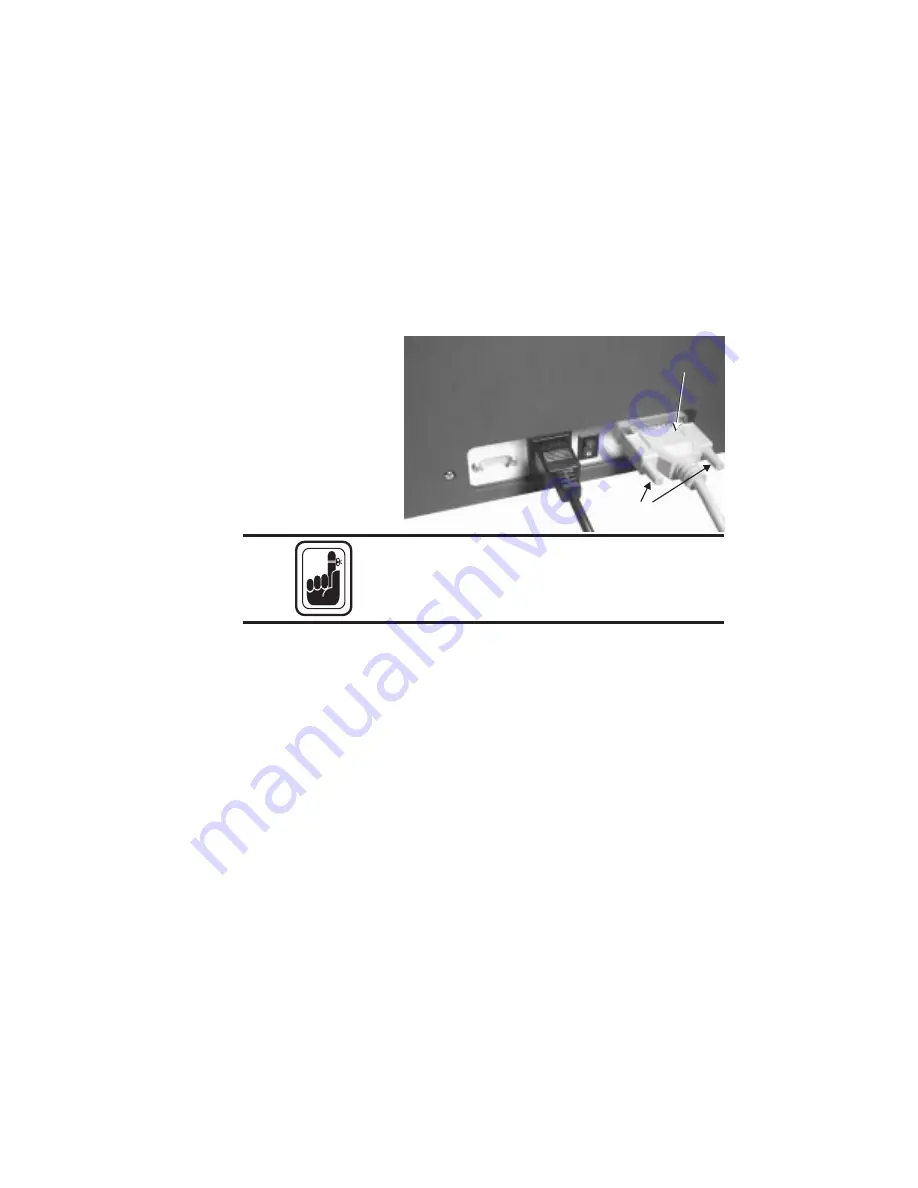
Attach and secure the supplied DB-25 (female)

to DB-25 (male) parallel printer cable between

the parallel port of the host computer and the

parallel interface connector on the back of the

printer.

Intermittent or unpredictable operation may

occur from unsecured connectors.

See Appendixes A and B for cable specifica-

tions and ordering information.

Step

Í

Applying Power

Set the power switch to ON (1). Note that mes-

sages appear on the LCD screens as the printer

cycles through the power-on sequence. Also

note that READY appears at the end of the se-

quence. If these events either fail to occur or an

ERROR message appears instead of READY,

refer to Appendix A - Trouble Shooting.

980179-001 Rev. A

9

Getting Started

Figure 1-5

Interface

Cable

Secure

Connector

Secure

Connector

Interface

Cable

Interface

Cable

Summary of Contents for PRIVILEGE P500

Page 1: ...User s Manual No 980179 001 Rev A 1997 Eltron International Inc User s Guide P500 and P600 ...

Page 2: ......

Page 3: ...300 FAX 33 0 240 834 745 FAX 44 0 1189 895 762 COPYRIGHT NOTICE This document contains information proprietary to Eltron International Incorporated This docu ment and the information contained within is copyrighted by Eltron International Incorporated and may not be duplicated in full or in part by any person without written approval from Eltron While every effort has been made to keep the informa...

Page 4: ... replace the equipment or any parts which are determined to be defective within this warranty period and which are returned to Eltron F O B factory of origin The warranty set forth above is exclusive and no other warranty whether written or oral is ex pressed or implied Eltron specifically disclaims the implied warranties of merchantability and fit ness for a particular purpose FCC NOTICE This equ...

Page 5: ...sociated con text Indicates a part that can operate at an elevated temperature capable of causing pain or a burn if touched Indicates an area where an electrostatic dis charge ESD can cause component damage Use a grounding wrist band Indicates that fiber deposits from fibrous clean ing materials e g cotton swabs can reduce print quality Indicates that exposure to dust and other air borne particles...

Page 6: ...especto a la Compatibilidad electromagnética y las Medidas de seguridad relativas al producto Basate sulla legislazione degli stati membri relativa alla compatibilitá elettromagnetica e alla securezza dei prodotti ber die Annäherung der Gesetze der Mitgliedsstaaten in bezug auf elektromagnetische Verträglichkeit und Produktsicherheit entspricht 89 336 EEC EMC Directive 92 31 EE EMC Directive 73 23...

Page 7: ...stments 32 Physical Processes 33 Cleaning The Printer 37 Cleaning Stationary Card Path Items 40 Cleaning the Card Feed Roller 41 Cleaning the Upper and Lower Cleaning Rollers 42 Print Head Cleaning 44 Cleaning the Transport and Platen Rollers 45 Cleaning Laminator Rollers 49 Magnetic Card Stripe Encoder 51 Introduction 51 Media Loading Orientation 52 Ensuring Data Reliability 52 Encoding 53 When t...

Page 8: ...bon 65 Printer Features and Options 68 Appendix B Supplies and Accessories 71 Accessories 71 Print Ribbons 72 Special Ribbons 72 Card Media 73 Miscellaneous Supplies 73 Installable Options 73 Appendix C Windows Card Printer Driver 75 Installation of Printer Drivers 75 Using the Windows 95 Driver 83 Using The Windows 3 1 Driver 92 Glossary 101 ...

Page 9: ...ivilege Series card printers offer a low cost high quality solution to those re quiring computer controlled printing and en coding of credit card style plastic cards Card applications include personalized identifica tion access control visitor membership pro motion and luggage card badges and tags 980179 001 Rev A 1 Eltron Privilege Multiple Station Card Printers ...

Page 10: ...and that can produce text using 2 resident fonts A 3 Track Magnetic Stripe Encoder option that writes and then read verifies data supporting cards with high or low coercivity magnetic stripes P500s can have either up or down facing stripe encoders P500s have Windows design and print user software and a Windows printer con trol driver that supports True Type fonts Efficiently designed to fit in min...

Page 11: ...ription P500CF 120385 001 Color Printer with Laminator P600 120284 001 Multiple Station Color Printer Options Option No s Expanded Mem ory P500 Low Coercivity Encoder High Coercivity Encoder Encodes Down facing Stripe Encodes Up facing Stripe Power Cord 104525 001 104674 001 104674 002 104674 003 104674 004 300020 001 120V 300020 002 230V 980179 001 Rev A 3 Getting Started ...

Page 12: ...rge of electrostatic energy that accu mulates on the surface of the human body or other surfaces can damage or destroy the print head or other electronic components used in this device 4 980179 001 Rev A Getting Started Packing Materials Foam End Cushons Foam End Cushons Supply Kit Printer Cable Power Cord Manuals Card Weight Card Catcher Software P500 Supply Kit Printer Cable Power Cord Manuals C...

Page 13: ... storage The print quality can be effected by dust body oils and acids i e finger prints and exposure to other for eign materials during unpacking or handling of the printer and media Check List Your Privilege Card Printer ships with the items listed below Printer Check for proper Model Interface Cable Power Cord 980179 001 Rev A 5 Getting Started ...

Page 14: ...Feeder Weight Card Catcher Manuals Printer User s Guide Software CD ROM WindCard Software Windows Driver s If any items are missing contact your dealer for replacement parts 6 980179 001 Rev A Getting Started ...

Page 15: ...on remove the printer from the carton and protective plastic bag AC power supplied to Privilege card printers must be current limited to 16 amps or less us ing an associated circuit breaker or other such electrical device Step Ë Attach Power Place the printer in a clean dust free loca tion that allows easy access to all sides of the printer Never operate the printer while it rests on a side or ups...

Page 16: ...ttach the AC power cord to the AC power re ceptacle in the rear of the printer Attach the AC power cord to a grounded elec trical outlet of the proper voltage and plug type 8 980179 001 Rev A Getting Started Figure 1 2 Power Switch Positions Switch OFF Switch ON Figure 1 3 Power Connection Figure 1 4 AC Outlet Connection ...

Page 17: ...s A and B for cable specifica tions and ordering information Step Í Applying Power Set the power switch to ON 1 Note that mes sages appear on the LCD screens as the printer cycles through the power on sequence Also note that READY appears at the end of the se quence If these events either fail to occur or an ERROR message appears instead of READY refer to Appendix A Trouble Shooting 980179 001 Rev...

Page 18: ...dows Program Manager s File pull down menu select Run Enter A SETUP or B SETUP if you placed the diskette in drive B Press the Enter key Follow the installation instructions on the screen to install the software Refer to Section 2 Operation for information on loading cards and ribbons and for initializ ing the printer for operation 10 980179 001 Rev A Getting Started ...

Page 19: ...See Appendix C for loading WindCard soft ware into other operating platforms and the Windows Printer Driver file 980179 001 Rev A 11 Getting Started ...

Page 20: ...12 980179 001 Rev A Getting Started ...

Page 21: ...ses Circuit Boards that contain a lithium batteries These batteries operate for long periods of time and replace ments may never become necessary Anyone replacing these batteries subjects his or herself to the following risk WARNING A Danger of Explosion exists if a battery is incorrectly replaced Replace only with the same or equivalent type recommended by the manufacturer Dispose of used batteri...

Page 22: ...rom its position while secured lift the rear case straight up Wires attached to the switches and LCDs restrict how far the rear case can sepa rate from the printer Therefore after freeing the rear case from the printer rest the rear case at a position that does not stress the wires 14 980179 001 Rev A Getting Started Figure 1 6 Screws Holding Rear Case Remove Philips Screws Remove Philips Screws R...

Page 23: ...to download all image data in a continu ous stream instead of the single color downloads followed by associated printing that occur without this addition Multiple card printing occurs much faster with this option in stalled Rear case removal gives access for this upgrade Before touching any of the circuit components on either the printer or the Expanded Memory board be sure to discharge any static...

Page 24: ...ch the connec tors such that the Expanded Memory board re mains confined within the boundaries of the CPU board not oriented to extend over the edge Installing the Memory Board Step Replace the bracket and printer case by revers ing the steps performed during their removal 16 980179 001 Rev A Getting Started Figure 1 9 Expanded Memory Installation ...

Page 25: ...Card Printer Note that both models have similar appearances except the P500 has a Lamina tor where the P600 has a second Print Station 980179 001 Rev A 17 Figure 2 1 Major Components Card Catcher Card Catcher Print or Lamination Station Print or Lamination Station Print Station Print Station Card Flip Card Feed Hopper Card Feed Hopper ...

Page 26: ...plies power to the printer Placing the switch in the OFF 0 position turns off the printer See Figures 1 1 and 1 2 in Sec tion 1 The POWER SWITCH also works in con junction with the Panel Button See the Panel Button on the following pages The following LCD messages can appear 18 980179 001 Rev A Operation Figure 2 2 Printer Controls and Indicators Module 2 LCD and Button Module 2 LCD and Button Mod...

Page 27: ... Progress LAMINATING Lamination in Progress OUT OF RIBBON New Ribbon Required OUT OF CARD More Cards Required COMMAND ERROR Command Parameter Error MECHANICAL ERROR Mechanical Problem ENCODING ERROR Read Verify Error READING ERROR Error Reading Mag Stripe ROTATION ERROR Card Flip Error TEMPERATURE ERROR Laminator Temp Wait COVER OPEN To Proceed Close Cover See Appendix A for troubleshooting tips 9...

Page 28: ...he empty core must face up Ribbon Preparation Step 2 Untape the end that fastens the ribbon end to the roll while leaving the tape attached on the supply side Ribbon Preparation Step 3 Unwind enough ribbon to reach the empty core and tape the end down If both the ribbon roll and the empty core are kept touching while the tape is refastened ribbon should be cen tered on the core An improperly prepa...

Page 29: ...procedures apply to Print Sta tions and Laminators as follows Ribbon Loading Step 1 Lift open the cover Ribbon Loading Step 2 Press down on the Print Lamination Head Re lease Latch to raise the Print Head The Print Head springs upward when released 980179 001 Rev A 21 Operation Figure 2 5 Raising the Cover Figure 2 6 Raising the Print Head Press Here to Raise Print Head Press Here to Raise Print H...

Page 30: ...m the supply side to span the dis tance between the Supply and Take Up spin dles Then at the same time slide the Supply and Take Up Cores onto their respective spin dles Make sure to push both fully onto the spindles Also make very sure that the ribbon comes off of the top of the Supply Spindle and feeds onto the top of the Take Up Spindle Note that for proper seating the take up cores of Laminati...

Page 31: ... click occurs at the latched down position 980179 001 Rev A 23 Operation Figure 2 7 Laminator Take Up Ribbon Core Alignment Align Notch with Spindle Screw Align Notch with Spindle Screw Figure 2 8 Ribbon Path Take Up Spindle Take Up Spindle Supply Spindle Supply Spindle ...

Page 32: ...24 980179 001 Rev A Operation Figure 2 9 Latching Down Print Head Press Here to Latch Down Print Head Press Here to Latch Down Print Head ...

Page 33: ...head Monochrome Ribbon No initialization re quired Hologram Ribbon No initialization re quired for ribbons that have no hologram placement requirements and no index marks P500 Lamination Ribbon Press and hold the left panel button until ribbon advances Only ribbons with die cut panels require Ini tialization Ribbon should stop with a black in dex mark located to the right of the Lamination Head Ha...

Page 34: ...s on dust or lint carrying surfaces i e table tops cloth com puters etc DO NOT place media with magnetic stripes on or near magnetic sources such as moni tors non electronic phones paper clip hold ers speakers etc Card Gate Adjustment The Card Gate serves to meter card feeds so that only one card feeds at a time If more than one card feeds a card jam occurs Each card thickness requires a different...

Page 35: ...itical for proper mechanical operation of the printer 980179 001 Rev A 27 Operation Figure 2 10 Card Hopper Card Gate Adjustment Card Gate Adjustment Card Feed Opening Card Feed Opening Card Feed Rollers Card Feed Rollers Card Weight Card Weight Cards ...

Page 36: ...ard of the desired thickness into the Card Feeder Open the Card Gate turn the gate adjustment knob clockwise until the end of the card can fit under the gate 28 980179 001 Rev A Operation Figure 2 11 Card Gate Adjustment Gate too High Gate too Low Gate About Right ...

Page 37: ...y to slide both cards through the gate If only the lower card fits the adjustment should suffice If both cards fit under the gate either lower the gate slightly or repeat the previous steps Card Gate Adjustment and Media Loading Step 4 Add cards of the same thickness to the Card Feed hopper sufficient for the printing needs and place the Card Weight on top of the stack During the first few print c...

Page 38: ...vent ESD damage keep the cover of the printer closed except during maintenance and media loading procedures An interlock pre vents card flips with the cover open With a fixed amount of space available the maximum number of cards the Card Feed hopper can hold varies as a function of card thickness as follows 100 of the 30 mil 0 762 mm cards 150 of the 20 mil 0 508 mm cards Note that P500s can only ...

Page 39: ...Printing When the ribbon and card media are loaded as previously described and the printer power is on the card printer is ready to print Printing requires the WindCard software a Windows software program the Windows printer driver or direct printer command level programming through the printer interface 980179 001 Rev A 31 Operation Figure 2 12 Card Catcher Tray ...

Page 40: ...d applies to Module 1 P600s print on both sides each module im ages a different surface Module 1 information appears on one side and Module 2 informa tion appears on the other Adjustments The card printers have no user adjustable fea tures except for the card gate adjustment see preceding pages 32 980179 001 Rev A Operation Figure 2 13 Color Printer Test Card P500 Print Sta tion Test Card P500 Pri...

Page 41: ... the card feeder gate adjustment Physical Processes A sensor signals when the feeder rollers deliver a card to the card transport rollers Cleaning Rollers remove dust or lint and transport roll ers accurately position the cards for printing lamination P500 Smart Card Contact Sta tion docking optional and magnetic stripe encoding also optional The print and laminator head s lower to the surface of ...

Page 42: ...e resin material onto cards Resin either transfers or not on a dot by dot basis Unlike dye sublima tion no in between conditions exist to produce a gray scale within each dot Particularly Bar Codes but also Text Lines and Rectangles of ten get composed using solid images Also Thermal Transfer ribbons come in a variety of colors other than black However bar code readers need black bar codes Overlay...

Page 43: ...nces to next panel Download print return card and synchro nize steps occur for ribbon panels Magenta M Cyan C Black Resin and Overlay For duplex two sided card printing cards move to the card flip where the lower side transfers to an up facing side P500 cards return again to the print head of the first sta tion for a repeat of the imaging sequence Often only black resin say for a bar code gets app...

Page 44: ...icant improvement occurs for multiple copy printing Because of their dual print stations P600s offer a great deal of versatility in choosing their op erations Users should explore the possibilities by selecting the command sequence that best suits their requirements After mapping out planned imaging decide which ribbons best suit these requirements Then decide where the ribbons should be installed...

Page 45: ...w away particles in the printer Air compres sors can contain rust inhibiting oil and may have ineffective moisture traps Oil and mois ture adversely affect print quality and when sprayed may spread contaminates throughout the printer Also canned air requires a very careful usage Avoid directing an air stream in a way that distributes particles from areas having a signifi cant particle contaminatio...

Page 46: ...aning A Cleaning Kit comprised of a spray can of alcohol and a package of cleaning cards suit able for a general cleaning but required for Magnetic Encoder head cleaning Cleaning products for the Privilege card printer are available directly from your Eltron distribu tor or call Eltron at 800 344 4003 for the distributor nearest you 38 980179 001 Rev A Operation Bend to Break and Release Fluid Ben...

Page 47: ...ems Card Guides Smart Card Contact Station and Magnetic Encoder Read Write heads Card Feed Roller Cleaning Rollers Print Head Transport and Platen Rollers 980179 001 Rev A 39 Operation Card Feed Rollers Cleaning Rollers Head Up Down Cam 2 places Transport and Platen Rollers Ribbon Take Up Card Path Module 1 Module 2 Card Flip Assembly Card Cooling P500 Magnetic Encoder Option Smart Card Station Op...

Page 48: ...pindles See Ribbon Loading in this section Using the Cleaning Kit Step 2 Moisten a Cleaning Card by spraying with al cohol Saturate the card but if alcohol drips from the card blot away the excess Using the Cleaning Kit Step 3 Place the moistened Cleaning Card in the In put Tray topped with the card weight If neces sary adjust the Card Gate for the card thickness Since this procedure calls for onl...

Page 49: ...s proceed as follows Cleaning the Feeder Rollers Step 1 Remove any cards from the Card Hopper Cleaning the Feeder Rollers Step 2 Clean the rollers using a Swab or Cleaning Pen To gain access to initially unexposed ar eas cycle the roller by applying the printer power while holding the Panel Button on for three 3 seconds see Test Card sequence in preceding description Let the roller air dry for two...

Page 50: ... the Cleaning Rollers Step 1 Remove any cards from the printer Open the printer cover To free an Upper Cleaning Roller gently pull the Spring Clip clear of the Upper Cleaning Roller pin Then remove the Upper Cleaning Roller Cleaning the Cleaning Rollers Step 2 Clean the Upper Cleaning rollers with running water Then allow the rollers to air dry without resting the rubberized part on a surface 42 9...

Page 51: ...rs Section 2 Cleaning the Cleaning Rollers Step 4 Reinstall the Upper Cleaning Roller First slide the shaft pin into the hole in the chassis oppo site the Spring Tab DO NOT touch the roller surface that contacts the media Snap the opposite shaft pin of the roller into the hole on the Spring Tab Without touching the body of the roller make sure the roller locks in place To avoid contami nation alwa...

Page 52: ...can remove dye or resin fused onto delicate Print Head elements Print Head Cleaning Step 1 Turn the printer power OFF Open the cover raise the print head and remove the ribbon from both spindles See Ribbon Loading in this Section The print head should only be cleaned with a solution of 99 pure Isopropyl Alcohol and a clean non fibrous foam swab Avoid touching the Print Head elements The release of...

Page 53: ...and Platen Rollers Along with the Cleaning Rollers these rollers move the cards between the Input Hopper and Card Catcher Except for the Platen these roll ers operate in pairs a lower drive roller and an upper pinch roller that holds cards against the drive roller Cleaning Platen and Transport Rollers Step 1 Open the Cover and unlatch and raise the Print and Lamination Heads Remove any rib bon Not...

Page 54: ...exposed areas by applying the printer power while holding the Panel Button pressed for three 3 seconds This is the Test Card sequence described in Controls and Indi cators in this section In the following steps avoid touching the Print Head A static discharge can damage delicate Print Head elements as well as internal circuits 46 980179 001 Rev A Operation Figure 2 19 Encoder Shroud Shroud Fastene...

Page 55: ...s Note that these ap pear under both Shrouds in P600s Cleaning Platen and Transport Rollers Step Í Using an alcohol moistened Swab clean the Cooling Station Roller P500 only 980179 001 Rev A 47 Operation Figure 2 20 Encoder Transport Rollers Encoder Rollers Encoder Rollers Figure 2 21 Cooling Station Rollers Cooling Station Rollers Cooling Station Rollers ...

Page 56: ... clean the Platen Roller Cleaning Platen and Transport Rollers Step Ï Using an alcohol moistened Swab clean the roller pair under the Print Head 48 980179 001 Rev A Operation Figure 2 22 Platen Roller Figure 2 23 Print Station Rollers Print Station Rollers Print Station Rollers ...

Page 57: ...ect the cards for Print Anomalies If Anomalies appear refer to Appendix A Troubleshooting Cleaning Laminator Rollers The Lamination head has two rollers an up per heated roller and a lower pressure roller Cleaning Laminator Rollers Step Ê Turn off power open the cover and unlatch and raise the Laminator head This is similar to the Ribbon Loading described in Section 1 980179 001 Rev A 49 Operation...

Page 58: ...alcohol moistened swab clean both Laminator rollers The upper roller can be turned manually to reach initially unexposed areas The lower roller can be turned using the same procedure that produces test cards Turn on power while hold in the Laminator button for three seconds Immediately turn off power to avoid heating the upper roller 50 980179 001 Rev A Operation Figure 2 25 Laminator Rollers Uppe...

Page 59: ...ercivity magnetic card stripes Introduction The general operation of a printer with an en coder option nearly duplicates that of models without this option P600 Encoders can reside in either Module 1 or Module 2 just past a Print Station P500 Encoders always reside in Mod ule 1 Encoder installations exist for either up or down facing magnetic stripes in both P500s and P600s Only use cards with flu...

Page 60: ...should face up or face down Improper hopper loads produce read errors Ensuring Data Reliability A read verify pass is always performed on all encoded cards to guarantee data integrity Either Software WindCard or command programming controls the Write and Read verify data processes 52 980179 001 Rev A Magnetic Card Stripe Encoder Figure 3 1 Magnetic Stripe Position Position Stripe Toward Back and t...

Page 61: ...llows E A Programmer s manual describes all the com mands including those related to the Encoder see Appendix B The following shows three examples that enter data initiate encoding and set up read write parameters that can be sent from either the Windows driver or directly using DOS e g COPY file name LPT1 or via a Text Editor and its Print facility with Privilege Driver selected Example 1 Downloa...

Page 62: ...n track 2 buffer B 3 09876 Enters 09876 in track 3 buffer E Encodes three tracks using buffer data and positions card for printing ME Ejects card from printer Example 3 Reset to ANSI ISO Command Result CDEW 1 A Resets track 1 encodes to ANSI ISO std CDER 1 Q Resets track 1 reads for ANSI ISO std CDEW 2 B Resets track 2 encodes to ANSI ISO std CDER 2 R Resets track 2 reads for ANSI ISO std CDEW 3 C...

Page 63: ...e cleaned Write and Read verify process has failed on more than one card See Appendix A Trou ble Shooting Cleaning the Encoder Turn OFF printer power Remove all card media and both the Supply and Take Up spools from the respective ribbon spindles Use the Cleaning Kit procedure described in Section 2 Adjustments Privilege card printers with Magnetic Card Stripe Encoders have no related user adjust ...

Page 64: ...ce dures described in this manual only allow El tron factory authorized technicians to service these printers NEVER loosen tighten adjust bend etc any part or cable inside of the printer The only user adjustable features of the Privi lege card printers are made in software or pro gramming and the card feeder gate adjustment 56 980179 001 Rev A Magnetic Card Stripe Encoder ...

Page 65: ... data Printers can have docking stations installed that can interface with Smart Card circuits Smart Card programming hard ware connects to a DB 9 connector on the rear panel Configurations with this option respond to commands that position the cards at the docking station as follows Command Result MS Moves card to Contact Station OS value introduces offset of value dots from Sta tion default 96 A...

Page 66: ...h that the edge closest to the contacts feeds first Adjustments No adjustments exist for Privilege printers with Smart Card programming stations other than the Card Feeder Gate Adjustment described in section 2 58 980179 001 Rev A Smart Card Contact Station Figure 4 1 Card Contact Position Up Facing Chip Contacts Up Facing Chip Contacts ...

Page 67: ...ters are made in software or program ming and the card feeder gate adjustment see Section 2 Smart Card Chip Interface When a command to the parallel printer inter face sends a card to the Smart Card Program ming station the printer connects the Smart Card Chip contacts to the female DB 9 con nector on the rear of the printer An attached external Smart Card Programmer uses the DB 9 as an interface ...

Page 68: ...wo card jam first Never pull the top card out of the printer Instead sequence the printer power with only the top card remaining the last card to enter the print path Remove all other cards from the path and card feeder Damage may occur to the contacts at the Smart Card chip programmer station if the top last card is not ejected by the printer 60 980179 001 Rev A Smart Card Contact Station ...

Page 69: ...indicates WAIT TEMPERATURE 1 Too Cold Associated Print or Lamination Head has not yet stabilized within proper operating range 2 Too Hot Associated Print or Lamination Head has exceeded a proper operating temperature typically due to high volume printing Printing appears faded or ex hibits poor quality 1 Clean the print head 2 Adjust the contrast and intensity in software or with programming 3 Ver...

Page 70: ...n 2 Check for broken ribbon Cards are present but LCD in dicates OUT OF CARD Card Feed Problem 1 Card Gate adjusted too low 2 Card Weight not in place 3 Cards or Card Feed rollers contaminated with oily deposit and require cleaning An LCD indicates READING ERROR Encoder Command Coding Error 1 Verify command syntax 2 Call technical support 3 Check card Hopper for proper stripe position An LCD indic...

Page 71: ... software Windows color printer driver or by pro gramming commands sent to the printer Print a Test Card and note the resis tance heat setting Verify the card values match those that appear on the print head label See following illustration Ribbon breaks during re synchronization of the color rib bon panel 1 Raise the related Print Head and synchro nize the ribbon The previous print process may ha...

Page 72: ...ingapore asiasup eltron com Latin America latinsup eltron com BBS 1 805 579 3445 The BBS supports data rates up to 28 8 BPS with No Parity 8 data bits and 1 stop bit n 8 1 Communications software should have an ANSI Terminal Mode not MS Win dows Terminal such as Q Modem CompuServe e mail 102251 1164 Customer Service 1 800 344 4003 For the name of a dealer in your area Technical Support FAX U S A 1...

Page 73: ...ays use Eltron approved card media and ribbons 980179 001 Rev A 65 Appendix A PRINTER DB 25 Pin No DB 25 Pin No Female DB 25 to Male DB 25 HOST STROBE DATA 0 DATA 1 DATA 2 DATA 3 DATA 4 DATA 5 DATA 6 DATA 7 ACK BUSY PAPER ERR READY INIT ERROR N A N A N A SIG GND SIG GND SIG GND SIG GND SIG GND SIG GND SIG GND STROBE DATA 0 DATA 1 DATA 2 DATA 3 DATA 4 DATA 5 DATA 6 DATA 7 ACK BUSY PAPER ERR READY I...

Page 74: ...tron s resin thermal transfer and die sublimation media are specifically de signed for Privilege card printers See Appen dix B Thermal Transfer Resin All print stations can use Thermal Transfer ribbon Resin offers more durability than dye sublimation with greater resistance to scratches and UV induced fading Dye Sublimation Printing requires dye sub limation ribbons with either black or Cyan C Mag...

Page 75: ... in 19 87mm Min 0 623 in 15 82mm Min 0 01 in 2 54mm Min gap 0 221 in 5 62mm max gap C1 0 210 in 3 54mm 0 631 in 7 54mm 0 395 in 8 25mm 0 790 in 21 87mm No print Area C1 VCC Supply Voltage C2 RST Reset Signal C3 CLK Clock C4 RFU C5 GND Logic Ground C6 VPP Programming Voltage C7 I O Data Input Output C8 RFU C1 C4 C5 C8 3 375 in 0 010 in 85 72mm 0 25mm 2 125 in 0 002 in 53 98mm 0 05mm Radius 0 125 in...

Page 76: ...olution 300 dots per inch 11 8 dot per millimeter Printing Technology Monochrome Thermal Transfer Color Dye Sublimation Print Time Typically 3 seconds per card monochrome Typically 45 seconds per card color Print Speed 0 5 ips Font Support Arial 22 Bold and Arial 28 Normal True Type fonts with the WindCard or Windows compatible printer driver to ac cess Windows resident fonts Bar Code Symbologies ...

Page 77: ...rift Smart Card Option Supports ISO 7816 Smart Card standards Card Dimensions Thickness Monochrome 10 mil to 40 mil 0 254 mm to 0 762 mm Color 20 mil to 30 mil 0 508 mm to 0 762 mm Standard Card Thickness 0 020 0 508 mm 0 024 0 610 mm 0 030 0 762 mm Width 3 375 85 6 mm typical Length 2 125 53 98 mm typical Card Feeder Stacks up to 150 20 mil cards Stacks up to 100 30 mil cards Power Requirements 1...

Page 78: ...r 30 5 in W x 12 5 in H x 10 1in D 775mm W x 320mm H x 258mm D With Card Catcher 34 6 in W x 12 5 in H x 10 1 in D 880mm W x 320mm H x 258mm D Weight Basic Unit 61 7 lb 28 1 kg Shipping 72 7 lb 32 9 kg 70 980179 001 Rev A Appendix A ...

Page 79: ...art number when placing an order Description Part Number Card Printer Parallel Interface Cable 6 DB 25 male to DB 25 female 300055 001 Windows Printer Driver WindCard Classic Software and Manual 205585 001 105525 004 User s Manual this Manual Programmers Manual 980179 001 980081 001 Lapel Clip Card Punch 806503 001 Video Kit camera video board 5 panel ribbon and 100 of the 30 mil PVC cards 104522 ...

Page 80: ... 800015 050 NOTES À Bar Codes require Black Resin printing Á Black ABS ribbon only used with ABS cards  Monochrome ribbons have no panel separations à Duplex printing when resin is required on both sides YMC Denotes Yellow Magenta Cyan colored panels Kr Denotes Black Resin panel Ks Denotes Black Dye Sublimation panel O Denotes transparent Overlay varnish Special Ribbons Description Part Number Ov...

Page 81: ...mil Low Coercivity Stripe 800017 102 30 mil High Coercivity Stripe 800017 103 Miscellaneous Supplies Description Part Number Drive Roller Cleaning Pens 12 800105 001 Print Head Cleaning Swabs 25 104526 001 Take up Ribbon Cores 10 205581 001 ID Card Lapel Clips 100 104527 001 Mag Head Cleaning Kit 104531 001 Installable Options Description Part Number Memory Expansion 104525 001 Replacement Print H...

Page 82: ...74 980179 001 Rev A Appendix B ...

Page 83: ...ssociated drive The execu table file may or may not start automatically depending on the CD ROM Auto Insert Notifi cation check box setting within Windows See Settings Control Panel System Device Man ager CD ROM If the Card Design Software screen fails to appear within about 30 seconds after CD insertion a manual start can be used as follows For Windows 95 1 Start the Windows Explorer and double c...

Page 84: ...starts has flags for several nations and a small button at the lower left corner Click on a flag to choose an associated lan guage Click on the button in the lower left corner to quit this software Subsequent screens have Back buttons that produce transitions back toward this screen so that a quit path exists from any point in the installation sequence 76 980179 001 Rev A Appendix C ...

Page 85: ...ndows 95 and Windows 3 1 Note that the Install Printers Driver screen has text that specifies the Drivers Folder as the loca tion of the driver file to be installed When re quested the path to the driver file must include this folder for example E driver win95 oemsetup inf Windows 95 Sequence When the Windows Printers dialog then ap pears Double click on Add Printer 980179 001 Rev A 77 Appendix C ...

Page 86: ...installation With confirma tion a screen then appears that allows the installation of either a network or local printer When the Add Printers Wizard dialog appears click on the Have Disk button This produces the Install From Disk dialog 78 980179 001 Rev A Appendix C ...

Page 87: ...ith a Driver folder that has a win95 folder and oem setup inf is targeted as the driver for installa tion However except for the driver folder a different path may be associated with the sys tem setup in use Click on the OK button to proceed Also click on OK in the dialog that requests installation of an associated disk At this point the Add Printer Wizard reappears with the Privilege Printer list...

Page 88: ...arameters Note that although selecta ble P500 and P600 printers cannot use a COM port limiting the choices to either LPT1 or LPT2 Windows 3 1 Sequence For Windows 3 1 the Printers dialog appears after the selection of Install Printer Driver Click on the Add button 80 980179 001 Rev A Appendix C ...

Page 89: ...In the next Printers dialog select Install Un listed or Updated Printer 980179 001 Rev A 81 Appendix C ...

Page 90: ...d file resides on the CD drive in its driver folder To find the file click on the Browse button or click on the OK button after replacing the A as in the following example Where the E may need to be replaced with the system CD drive designation used E driver win3 1 oemsetup inf 82 980179 001 Rev A Appendix C ...

Page 91: ... driver installation the Privilege printer becomes a selectable device accessed from the dialog that appears with selection of File Print Therefore users can send images created in an associated application to the printer for card imaging Print dialogs offer settings that reflect the uniqueness of the selected driver Like other printers Privilege printers have many opera tional parameters that a u...

Page 92: ...To reach the following dialog click on the Properties button First note the tabs at the top of this dialog Separate descriptions for each tab appear in the following 84 980179 001 Rev A Appendix C ...

Page 93: ...led in the card printer Note however that the other settings in this grouping prescribe variations on ribbon use Card orientation settings allow the matching of the card orientation to the print file image ori entation Dithering refers to the format used to blend col ors Users should choose the format that pro duces the most pleasing results 180 Rotation flips an image upside down Ei ther or both ...

Page 94: ...to receive varnish can be changed Note that the card origin lies at the upper left corner and that dot values correspond to 300 dots per inch Users can select preestablished varnish map ping for smart cards and magnetic stripe cards by clicking on the radio buttons below the black area Further down appear selections that implement importation of a bit map that defines varnish mapping Any bit map i...

Page 95: ...980179 001 Rev A 87 Appendix C ...

Page 96: ...The Head Settings tab offers sliders that con trol the contrast and intensity related to each print ribbon panel 88 980179 001 Rev A Appendix C ...

Page 97: ... see Section 3 examples using Windows driver This tab then allows users to specify which non recording characters in the document file specify Start of data and End of data Note that data for each track requires this format and a track number must follow the Start characters 980179 001 Rev A 89 Appendix C ...

Page 98: ...ection tab has sliders that al lows color adjustments for red green and blue both intensity and contrast These settings can serve to make card images match correspond ing monitor images 90 980179 001 Rev A Appendix C ...

Page 99: ...e Lamination Station in P500 card printers This tab allows enabling or disabling of lamination specification of the Lamination Station ribbon type the card speed through the laminator and the lamination temperature 980179 001 Rev A 91 Appendix C ...

Page 100: ...rd Windows software applications These features are ac cessed through the Printers control panel in the Program Manager Main group For a Privilege printer select PRIVXXX where XXX designates the desired installed driver Double click on the PRIVXXX or select Connect to set the printer to the correct printer port 92 980179 001 Rev A Appendix C ...

Page 101: ...nter setup or controls are accessed through the Printers display see previous page Select Setup Select the print orientation by clicking on the Portrait or Landscape buttons See display above 980179 001 Rev A 93 Appendix C ...

Page 102: ...nd how a black panel participates in the print ing A Head Setting button produces a dialog box that allows intensity level adjustments for YMCK and the Overlay Varnish Check boxes enable or disable duplex printing data compression and a preview of the image awaiting printing You can rotate images 180º from either Landscape or Portrait to avoid con flicts with a magnetic stripe or a punch out for a...

Page 103: ...resents overlay material The white area represents area without overlay material Overlay varnish protects printed images Never use an overlay on magnetic stripes smart chips or bar codes The values specify the top left and bottom right corner positions in dots of an overlay rectangle where a dot represents 0 0033 inches 0 0847 mm 980179 001 Rev A 95 Appendix C ...

Page 104: ...a custom overlay mask The file dimension in dots is a maximum 1008 dots wide by 624 dots high Select the Varnish pull down to control the Overlay Varnish material mask area and type Select the Film Type pull down menu to se lect the ribbon panel type in use 96 980179 001 Rev A Appendix C ...

Page 105: ...trol how the black ribbon panel participates in the printing process Black Resin panels do not participate in printing composed of CMY color graphics Black Resin panels primarily serve to print bar codes and fonts 980179 001 Rev A 97 Appendix C ...

Page 106: ...e heat levels applied that transfer black resin or over lay varnish material The Dye Color Intensity settings control the maximum amount of heat used to sublimate the color dye The Dye Color Contrast controls the mini mum color intensity level for a color Setting a Contrast V B or Dye Color Intensity level to high or low may result in poor image quality or ribbon damage 98 980179 001 Rev A Appendi...

Page 107: ...r the com mand s in the space designated Press Execute to send the string to the printer Press Finish to close the Printer Control box The following may prove useful in checking the printer interface along with associated command activated components Command Result A Prints Test Card ME Ejects Card D Lowers Print Head M Raises Print Head P Runs Stepper 2 sec R data Where data Head Resistance 98017...

Page 108: ...ngs either enable or disable the benefits of the Expanded Memory option Enabled bit maps for each of the color YMC and mono chrome KO panels download together Dis abled bit maps download separately for each ribbon panel Settings for Offset determine the origin for card graphics 100 980179 001 Rev A Appendix C ...

Page 109: ... of a magnetic stripe Butterfly Pouch An unlaminated ID badge with a hinge running along one edge into which the prepared ID card is inserted and laminated Card Commonly used generic term for magnetic stripe media regardless of shape construction and material e g magnetic stripe cards badges tickets forms Card Pass A card pass or pass occurs when the Print Head is engaged and making contact with t...

Page 110: ...olors using YMCKO and YMCKOK ribbons where colors and sublimation black comes from YMC combinations a thermal transfer black comes from the K and a protective transparent overlay comes from the O CMYK Cyan Magenta Yellow and Black are the print colors used by press men when using the four color process Data IBM Size An ID badge or card measuring 2 328 wide by 3 250 long Debit Card a A card with va...

Page 111: ...ldup on people exposed to dry conditions Format The set of unique bit string patterns of Zeros and Ones correspond ing to the set of data characters used in magnetic stripe encoding many differ ent data formats are used the best known being the ANSI ISO and ALPHA formats High Energy Stripe High coercivity magnetic stripe usually above 3000 oersteds sometimes mistakenly understood to have a higher ...

Page 112: ... of material consisting of oriented ferromag netic particles rigidly held together by a resin binder and bonded to a nonmag netic carrier medium such as paper or plastic Media The material used e g magnetic stripes cards ribbons etc Mil One thousandth of an inch Optical Memory Optically coded cards depend upon varying transparency densities arranged in rows columns or spots read by a system of lig...

Page 113: ...nually operated reader with a long narrow channel slot through which the magnetic stripe edge of the card is pushed T A Time Attendance systems or applications Track A strip of specified width and location running the length of the mag netic stripe on which data is encoded Track 1 2 and 3 are specific track loca tions defined by ANSI ISO standards Watermark Magnetic A card containing small oxide p...

Page 114: ...FAX 1 805 579 1808 e mail sales eltron com Eltron House Molly Millars Lane Wokingham RG41 2QZ England Phone 44 0 1189 770 300 FAX 44 0 1189 895 762 e mail eurosales eltron com 836 Arlington Heights Rd 357 Elk Grove IL 60007 Phone 1 847 584 2714 FAX 1 847 584 2725 e mail latinsales eltron com 07 01 Trademart Singapore 60 Martin Road Singapore 239067 Phone 65 73 33 123 FAX 65 73 38 206 e mail asiasa...

Reviews: