


A
n
al
yz
er
U
se
r
Gu
ide
Internet
Protocol
None
Wireshark
Exports filtered IP carrier protocols like
DUN, BNEP from active Overview
Spectrum
None
CSV
Exports spectrum RSSI samples fopr each
channel.
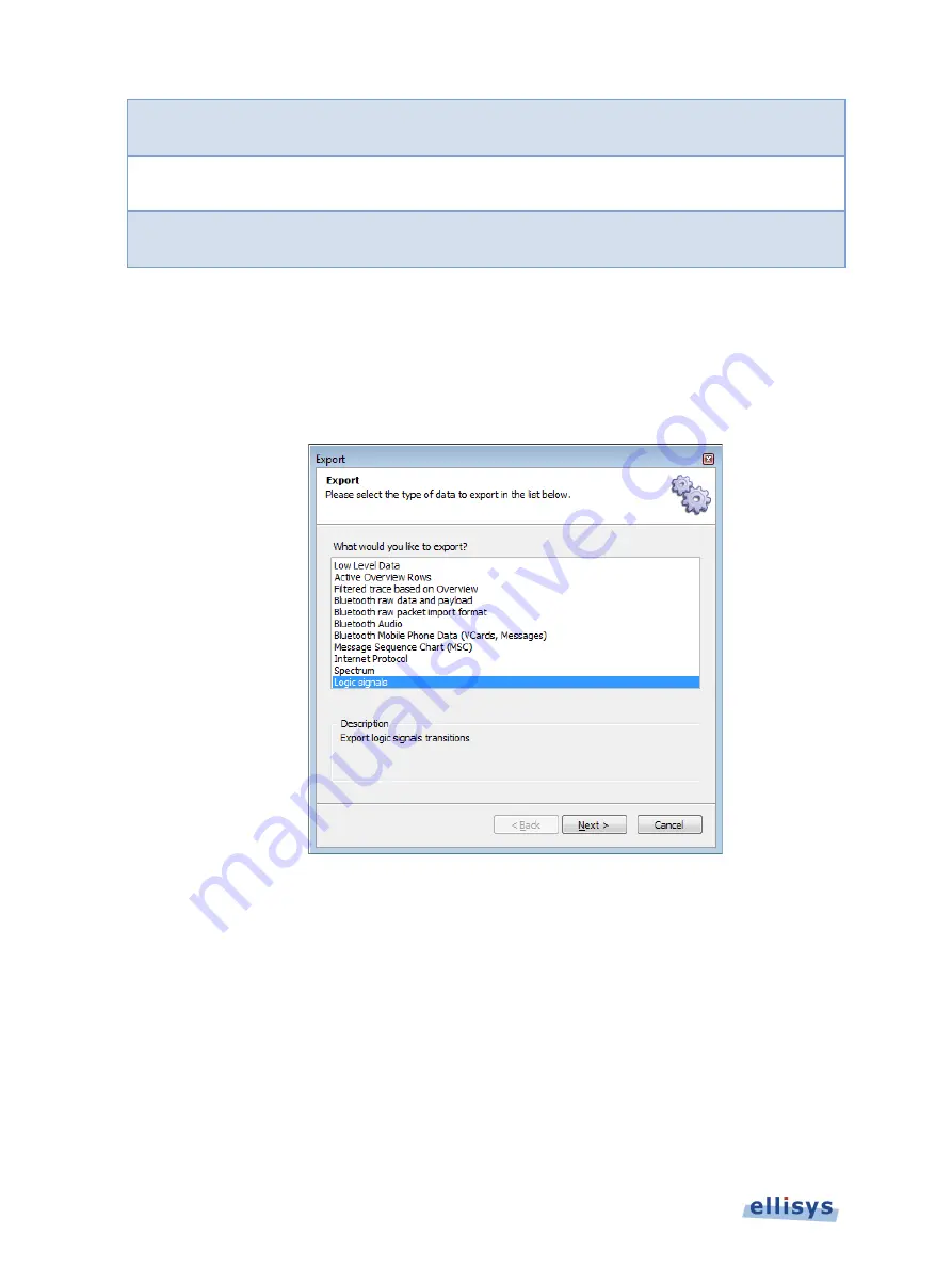
Logic
Signals
None
CSV
Exports logic signal transitions.
To use the export feature:
1.
Open the desired capture file.
2.
Select
File | Export
from the menu.
The
Export
menu appears:
3.
Select the desired export method.
4.
Click on
Next
.
5.
Select any export options as applicable and click on
Next
.
42 of 201 |
Managing Capture Files


