


Model 75 service manual, SM75_0413 Page 5
eskridge, inc. olathe, KS. 913-782-1238 www.eskridgeinc.com
reassembly
1)
Rebuild primary planet carrier assembly in reverse order
using any needed new parts.
2)
Install bearing
(7e & 7f)
into planet gear
(7b)
. Place one
thrust washer
(7D)
on each face of the planet gear. Install
gear assembly into carrier
(7a)
.
3)
Planet shafts
(7c)
should be installed with the chamfered
end of the 3/16 inch hole towards the outside diameter of the
carrier
(7a)
; this will aid in alignment of holes while inserting
roll pins
(7g)
.
4)
Drive roll pin
(7g)
into the carrier hole and into the planet
shaft to retain the parts. Repeat for remaining planet gears.
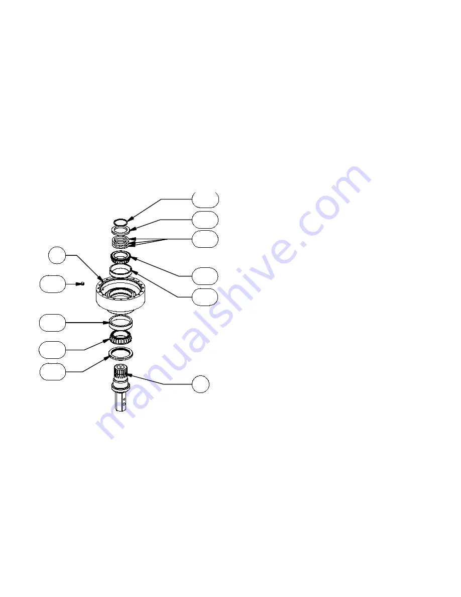
base Subassembly
(items 1, 8, 11a, 12a, 12b, 12c, 12D, 14a, 16a, 16b, 16c)
Disassembly
1) Remove the retaining ring
(16c)
, support ring
(16b)
and
shims
(16a)
.
caution: Since the output shaft is no longer retained, care
should be taken to avoid personal injury. care should also be
taken not to damage it when it is pressed through base.
2)
Base
(1)
should be set shaft side down, as shown, on a plate
or table. Press output shaft
(8)
through the bottom of base
by applying a load to top end (internal end) of shaft until it
passes through inner shaft bearing cone
(12a)
.
note: removing the shaft from the base assembly damages
the shaft seal and the seal will need to be replaced.
3)
A gear puller may be used to remove the outer bearing cone
(12c)
from the shaft
(8)
. If reusing old bearing cone, do not
pull on or damage roller cage. Remove the shaft seal
(11a)
from the shaft for replacement.
4)
Inspect inner and outer bearing cups
(12b & 12D)
. If cups are
damaged, drive them out using a brass drift and utilizing the
bearing knock-out notches in the base
(1)
reassembly
1)
Clean all foreign material from magnetic oil plug
(14a)
locat-
ed on the side of the base
(1)
.
2)
Place base
(1)
(output side up, opposite shown) on the ta-
ble.
3)
Apply a layer of lithium or general purpose bearing grease to
the roller contact surface of outer bearing cup
(12D)
.
4)
Press outer bearing cone
(12c)
(large end down as shown)
onto the shaft
(8)
until it seats against the shoulder.
note: Press bearing cone onto output shaft by pressing on in-
ner race only. Do noT press on roller cage, as it may damage
bearing.
5)
Place the shaft
(8)
with the bearing
(12c)
into the base
(1)
.
6)
Flip this assembly, resting the base
(1)
on the end of the out-
put shaft
(8)
.
7)
Apply a layer of lithium or general purpose bearing grease to the
roller contact surface of the inner bearing cup
(12b)
. Press the
inner bearing cone
(12a)
(large end up as shown) onto the
shaft
(8)
until it is seated against inner bearing cup.
8)
Without the shaft seal
(11a)
installed, the preload may result
in a rolling torque that varies between 50 to 300 in-lb. The
bearing preload should be tailored to your application; a low-
speed application may require a high pre-load, high-speed
applications usually benefit from low pre-load. Adding shims
(16a)
will increase the pre-load on the bearing set. Determine
your pre-load requirement and install shims to obtain this pre-
load. Place the support ring
(16b)
over the shims
(16a)
and
install the retaining ring
(16c)
into the groove in the shaft
(8)
.
9)
Lubricate inner lip of new shaft seal
(11a)
and slide it onto the
shaft
(8)
and over the shaft seal diameter then press the seal
into the base bore
(1)
.
all subassembly service or repairs should be complete at this
time. continue to unit assembly to complete unit buildup.
unit assembly
1)
When all subassemblies are complete, the unit is ready to be
assembled.
2)
Install the Stage II carrier assembly
(7)
onto the output shaft;
align the splines of the carrier
(7a)
with the splines of the
shaft
(8)
and slide the carrier onto the shaft.
3)
Lubricate o-ring
(11b)
and install on the pilot of the
Stage II ring gear
(3)
.
caution: hold ring gear by outside or use lifting device to pre-
vent injury.
5)
Install Stage II sun gear
(9)
into Stage II carrier assembly
(7)
.
Place thrust washer
(10a)
onto Stage II carrier
(7a)
.
6)
Align gear teeth of ring gear
(3)
with the gear teeth of the
planet gears
(7b)
and place on base. Align mounting holes
of ring gear with holes in base using the scribed line made
during disassembly for reference.
16B
16C
16A
12A
12B
14A
1
12D
12C
11A
8
Summary of Contents for Digger Derrick
Page 2: ......
Page 37: ...Nomenclature EEC 0169 V1 0 Nomenclature...
Page 39: ...Platform Safety EEC 0061 V1 1 Platform Safety...
Page 54: ...Platform Safety EEC 0061 V1 1 Platform Safety...
Page 116: ...Jib Operation EEC 0044 V1 1 Jib Operation E C B A C2 C1 B...
Page 161: ...Digger Derrick Labels EEC 0171 V1 0 Digger Derrick Labels...
Page 163: ...Digger Derrick Labels EEC 0171 V1 0 Digger Derrick Labels 12 20 22 23 24 28 29...
Page 164: ...Digger Derrick Labels EEC 0171 V1 0 Digger Derrick Labels 30 38 39...
Page 170: ...Digger Derrick Specs EEC 0170 V1 2 Digger Derrick Specifications...
Page 172: ......
Page 173: ......
Page 174: ......
Page 175: ......
Page 176: ......
Page 179: ...3 2 1 4 6 5 3 2 1 4 6 5 3 2 1 4 6 5 TITLE...
Page 180: ......
Page 181: ......
Page 182: ......
Page 183: ......
Page 193: ...Bolt Torque EEC 0016 V1 2 Bolt Torque...
Page 199: ...Four Section Boom Operation common EEC 0021 V1 3 Four Section Boom Operation...
Page 227: ...4 HYDRAULIC SCHEMATIC...
Page 240: ...17 EXPLODED ISOMETRIC ASSEMBLY DRAWING...
Page 245: ...4 5200S...
Page 246: ...5 6000S...
Page 247: ...Elliott Operating Manual...
Page 277: ...Elliott Calibration and Troubleshooting Manual...
Page 312: ...36 W450321A 09 12...
Page 362: ......
Page 375: ...Appendix B Parts Index ELLIOTT Built for You Digger Derrick Truck B 1...