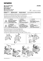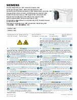
2 / 2
HRN-33 /
HRN-63
HRN-34 /
HRN-64
HRN -35
HRN-37 /
HRN-67
HRN-34
Umax
Un
Umin
15-18
LED
LED U
t
t
H
H
HRN-33, HRN-37
>
Umax
Un
Umin
15-18
LED Un
LED U
H
H
t
t
HRN-35
>
Umax
Un
Umin
15-18
25-28
LED Un
LED U
H
H
t
t
<t
<t
HRN-63,HRN- 64, HRN-67
Umax
Un
Umin
LED>Un
15-18
t
t
Warning
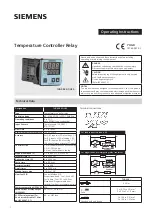
Technical parameters
Devices line HRN-3x and HRN-6x are constructed to be connected into 1-phase main or
DC circuits (according to types, it is necessary to observe voltage ranges) and must be
installed in accordance with regulations and standards applicable in a country of use.
Installation, connection, setting and servicing can be done only by a person with an
adequate qualifi cation who has read and perfectly understood this manual and function of
the device. The device contains protections against over-voltage peaks and disturbances in
the supply main. To assure correct function of these protections, there must be front-ended
suitable protections of higher degree (A, B, C) and according to a standard switched devices
(contactors, motors, inductive loads etc.) must be screened. before installing it is necessary
to make sure that the device is not energized and main switch is in position OFF. Do not
install device to sources of excessive electromagnetic disturbances. By correct installation
of the device, ensure perfect air circulation so the maximal operational temperature of the
device is not exceeded when operated 24 hours a day with higher ambient temperature. Use
screwdriver width approx. 2 mm to install and set the device. Please keep in mind that it is a
fully electronics device while mounting it. Correct function of the device is also depended
on the type of transport, storing and handling. In case you notice any damage, deformation,
malfunction or missing piece, do not install the device and claim it at the seller. The device
can be dismounted, recycled or stored at protected dumping-place after its lifetime.
Function
Supply and measuring
Terminals:
Voltage range:
Power input:
Max. dissipated power
(Un + terminals):
Upper level (Umax):
Bottom level (Umin):
Max. permanent:
Peak overload < 1 ms:
Time delay:
Accuracy
Setting accuracy (mech.):
Repeat accuracy:
Dependance on temperature:
Tolerance of limit values:
Hysteresis
(from fault to normal):
Output
Number of contacts:
Current rating:
Breaking capacity:
Inrush current:
Switching voltage:
Output indication:
Mechanical life:
Electrical life (AC1):
Other information
Operating temperature:
Storage temperature:
Electrical strength:
Operating position:
Mounting:
Protection degree:
Overvoltage cathegory:
Pollution degree:
Max. cable size (mm
2
):
Dimensions:
Weight:
Standards:
A1 - A2
AC 48 - 276 V / AC 48 - 276 V / AC 24 - 150 V /
50 - 60 Hz DC 6 - 30 V 50 - 60 Hz 50 - 60 Hz
AC max. 1.2 VA / DC max. 1.2 VA / AC max. 1.2 VA / AC max. 1.2 VA /
0.5 W 0.5 W 0.5 W 0.5 W
4 W 4 W 6 W 4 W
AC 160 - 276 V DC 18 - 30 V AC 160 - 276 V AC 80 - 150 V
30 - 95 % Umax 35 - 95 % Umax 30 - 95 % Umax 30 - 95 % Umax
AC 276 V DC 36 V AC 276 V AC 276 V
AC 290 V DC 50 V AC 290 V AC 290 V
adjustable, 0 - 10 s
5 %
< 1 %
< 0.1 % / °C (°F)
5 %
2 - 6 % of adjusted value
(only HRN-33, HRN-34, HRN-35, HRN-37)
16 A / AC1
4000 VA / AC1, 384 W / DC
30 A / < 3 s
250 V AC / 24 V DC
red / green LED
3x10
7
0.7x10
5
-20 °C to 55 °C (-4 °F to 131 °F)
-30 °C to 70 °C (-22 °F to 158 °F)
4 kV (supply - output)
any
DIN rail EN 60715
IP40 from front panel, IP20 terminals
III.
2
solid wire max. 1x 2.5 or 2x 1.5,
with sleeve max. 1x 2.5 (AWG 12)
90 x 17.6 x 64 mm (3.5˝ x 0.7˝ x 2.5˝)
62 g (2.2 oz.) 75 g (2.6 oz.) 86 g (3 oz.) 61 g (2.2 oz.)
EN 60255-6, EN 61010-1
Function HRN-63, 64, 67:
Monitoring relay line HRN-6x serves to monitor levels of voltage in single-phase or
DC circuits. Monitored voltage is in the same time also supply voltage. It is possible to
set two independayt levels of voltage. When Umax is exceeded, output is activated.
In case voltage level falls below Umin, output is deactivated. This combination is
advantageous when full absence of supply voltage is understood as faulty state.
as well as voltage drop in the frames of set level. To eliminate short voltage peaks
in the main there is time delay which can be set in a range of 0 - 10 sec. Such delay
applies in case of going from overvoltage to undervoltage. In case of returning from
undervoltage to overvoltage this delay doesn’t apply. Thanks to changeover output
contacts it is possible to reach various confi gurations and functions according to
requirements or an application.
Legend:
Umax - upper adjustable level of voltage
Un - measured voltage
Umin - bottom adjustable level of voltage
15-18 - switching contact of output relay No.1
25-28 - switching contact of output relay No. 2
LED ≥ Un - green indicator light
LED U - red indicator light
LED U> - red indicator light
H - Hysteresis
Function HRN-33, 34, 35, 37:
Monitoring relay series HRN-3x monitores level of voltage in single - phase and DC
circuits. Monitored voltage serves also as supply voltage. It is possible to set two
independayt levels of voltage, when exceeded the output is activated. HRN-33, HRN-
34 and HRN-37 - in normal state the output relay is permanently switched. It switches
off when there is a below or above defl ection. This combination of connection of the
output relay is advantageous when the full failure of supply (monitored) voltage is
considered to be a faulty state in the same way as a decrease of voltage within the set
level. Output relay is in both situations always switched off . Diff erently HRN-35 version
uses independayt relay for each level, in normal state it is switched off . If the upper
level is exceeded (for example overvoltage) 1 relay switches on, when the bottom
level (e.g. undervoltage) is exceeded 2 relay switches. It is thus possible to see the
particular faulty state. To eliminate short peaks in the main the time delay, which is
possible to be set in range 0 - 10 s, is used. It functions when changing from normal to
faulty state and prevents unavailing pulsation of the output relay caused by parasitive
peaks. Time delay doesn´t apply when changing from faulty to normal state, but
hysteresis (1 - 6 % depends on the voltage setting) apply. Thanks to changeover
contacts it is possible to get other confi gurations and functions according to actual
requirements of the application.
1x changeover /
SPDT (AgNi /
Silver Alloy)
1x changeover /
SPDT (AgNi /
Silver Alloy)
1x chang. for each
level of voltage,
(AgNi)
1x changeover /
SPDT (AgNi /
Silver Alloy)


