


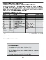


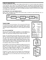


VOLTAGE ANALYSIS OF POWER SUPPLY
Proceed with the voltage analysis only if the resistance readings were satisfactory.
Place the top panel on the unit. If any capacitors are inserted backwards, the panel will shield you if
they explode. Make sure that the ON/OFF switch is in the OFF position. Plug the line cord into the 120VAC
power source. Turn the unit on and let it sit for a few minutes. Turn OFF the ON/OFF switch and remove the
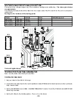
top panel, placing it along the left side of the trainer. Turn ON the ON/OFF switch and measure the voltage point
as listed in the chart below. The values given are approximate.
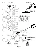
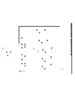
See Figure V for locations of the testing points.
From
To
Circuit
Volts
Volts Measured
15
GND
+12V Regulator Input
+21V
B3
GND
+12V Regulator Output
+12V
16
GND
-12V Regulator Input
-21V
B2
GND
-12V Regulator Output
-12V
17
GND
+5V Regulator Input
+12.5V
B4
GND
+5V Regulator Output
+5V
18
GND
+20V Regulator Input
+28V
25
GND
Voltage ADJ +20V Regulator
CCW 0V CW +18V
+20
5 pin connector
GND
+20V Output
CCW +1.25V CW +20V
19
GND
-20 Regulator Input
-28V
26
GND
Voltage ADJ -20V Regulator
CCW 0V CW -18V
-20
5 pin connector
GND
-20V Output
CCW -1.25V CW -20V
15VAC
15VAC
30VAC
30VAC
5-pin
5-pin
connector
connector
left
right
«
«
«
«
«
+30%
CCW - Counter-Clockwise CW - Clockwise
r
Turn unit off.
-17-
FUSE REPLACEMENT
1. Turn the trainer off and unplug it from 120VAC power source.
2. Unscrew fuse holder cap and remove fuse.
3. Use only a 1.25A fuse. Larger fuses or other fuse bypass will void the war-
ranty of the trainer.
4. Place the new fuse into the fuse holder cap and screw it back into the holder.
5. Plug trainer into 120VAC power source and turn the unit on.
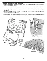
Place the top panel on top of the unit.
Summary of Contents for XK-550K
Page 37: ...SCHEMATIC DIAGRAM ANALOG SECTION 36 ...
Page 50: ...SCHEMATIC DIAGRAM 49 ...


