


-34-
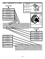
Figure M
Figure N
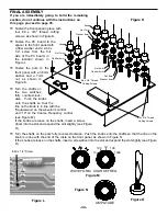
Figure L
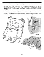
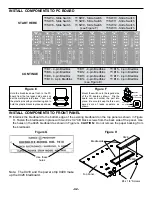
FINAL ASSEMBLY
If you are immediately going to build the remaining
section, do not continue with the instructions on
this page, proceed to page 35.
r
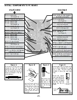
Fasten the front panel in place with
four #6 x 3/8” thread cutting
screws, as shown in Figure K.
r
Fasten the PC board to the
spacer to the front panel with
a fiber washer and a 4-40 x
1/4” screw from the foil
side of the PC board, in
the location shown in
Figure L.
r
Fasten the pots to the
front panel with an 8mm
washer and a 7mm
nut, as shown in
Figure K.
r
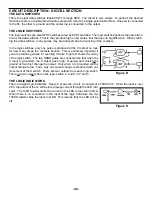
Turn the shafts on
the two switches
fully counter-clock-
wise.
Push the knobs
onto the shafts so that the
line on the knob is in line with the
“Squarewave” on the waveform control
and “10” on the Coarse Frequency control
(see Figure M).
If the knobs are loose on the shafts, insert a screw-
driver into the slot and expand the slot slightly (see Figure
O).
r
Turn the shafts on the pots fully counter-clockwise. Push the knobs onto the shafts so that the line on the
knob is in line with the end of the circle on the front panel, as shown in Figure N.
If the knobs are loose on the shafts, insert a screwdriver into the slot and expand the slot slightly (see Figure
O).
Knob
Nut 7mm
Washer 8mm
#6 x 3/8” Thread
Cutting Screws
#6 x 3/8” Thread
Cutting Screws
Nut 8mm
Washer 9mm
Nut 8mm
Washer 9mm
Knob
Nut 7mm
Washer 8mm
Figure K
4-40 x 1/4” Screw
Figure O
WAVE FORM COARSE FREQ
AMPLITUDE
10
100
1K
10K
100K
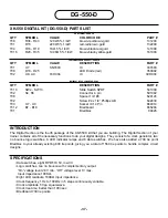
Summary of Contents for XK-550K
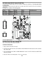
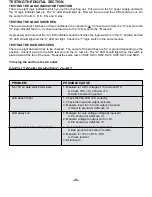
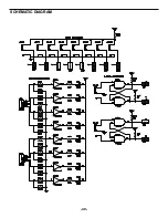
Page 37: ...SCHEMATIC DIAGRAM ANALOG SECTION 36 ...
Page 50: ...SCHEMATIC DIAGRAM 49 ...


