


-22-
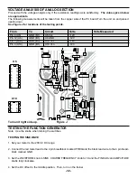
CIRCUIT DESCRIPTION
The power supply features two variable output voltages and three fixed 12V, -12V and 5V variable output voltages are
1.25V to 20V and -1.25 to -20V at up to 1 ampere maximum current. All supplies are regulated to better than .2V
when going from no load to full load. Varying the input AC voltage from 105 to 135V will have practically no effect on
the output voltages. This is because of the specially designed ICs used in the XK-550 Digital/Analog Trainer. Severe
overloading or even shorting the output circuits will not damage the supplies. Special turn-off circuits in the ICs sense
the overload and turn off the output.
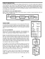
THE POSITIVE 1.25 TO 20V POWER SUPPLY
Figure 1 shows a simplified circuit diagram of the positive supply. It consists of a power transformer, a DC rec-
tifier stage and the regulator stage.
TRANSFORMER
The transformer T1 serves two purposes. First, it reduces the 120VAC input
to 17VAC to allow the proper voltage to enter the rectifier stages. Second,
it isolates the power supply output from the 120VAC line. This prevents the
user from dangerous voltages should he or she be standing in a grounded
area.
AC TO DC CONVERTER
The AC to DC converter consists of diodes D1, D3 and capacitor C1.
Transformer T1 has two secondary windings which are 180 degrees out of
phase. The output at each winding is shown in Figure 2A and 2B.
Diodes are semiconductor devices that allow current to flow in only one
direction. The arrow in Figure 3 points to the direction that the current will
flow. Only when the transformer voltage is positive will current flow through
the diodes. Figure 3 shows the simplest possible rectifier circuit. This cir-
cuit is known as a half-wave rectifier. Here the diode conducts only half of
the time when the AC wave is positive as shown in Figure 2C. Use of this
circuit is simple but inefficient. The big gap between cycles require much
more filtering to obtain a smooth DC voltage.
By the addition of a second diode and transformer winding we can fill in the
gap between cycles as shown in Figure 4. This circuit is called full-wave rec-
tification. Each diode conducts when the voltage is positive. By adding the
two outputs, the voltage presented to capacitor C1 is more complete, thus
easier to filter, as shown in Figure 2E. When used in 60 cycles AC input
power, the output of a full wave rectifier will be 120 cycles.
Capacitor C1 is used to store the current charges, thus smoothing the DC
voltage. The larger the capacitor, the more current is stored. In this design,
1000
µ
F capacitors are used, which allows about 5 volts AC ripple when one
amp is drawn.
Figure 1
Simplified diagram of positive power supply
120VAC
Input
17VAC
20VDC
1.25 - 15V
Regulated
Output
Transformer
120V to 17V
AC to DC
Converter
Voltage
Regulator
Figure 2
Figure 3
Figure 4
Voltage Waveform for Supply
A) Transformer
Winding AB
B) Transformer
Winding BC
C) Output of
diode D1.
D) Output of
diode D2.
E) Total of diodes
D1 & D2.
20
F) Output of capacitor C1
Ripple depends on load
current (expanded).
Half Wave Rectifier
Full Wave Rectifier
Summary of Contents for XK-550K
Page 37: ...SCHEMATIC DIAGRAM ANALOG SECTION 36 ...
Page 50: ...SCHEMATIC DIAGRAM 49 ...


