


-16-
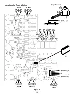
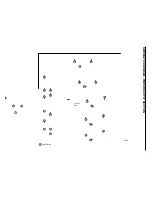
Locations for Testing Points
•••
21
19
26
•••
18
20
25
•••
22
27
17
5 pin connector left
5 pin con20
5 pin connector right
5 pin connector -20
GND
Ground
•••
29
16
24
•••
15
28
23
9
8
7
6
5
4
10
11
12
13
14
+20V
Po
t
-20V
Po
t
Plug of line cord
1
3
2
Figure O
B1
LM-7812
LM-7912
LM-7805
LM-317
LM-337
On test points 4 - 14
use the leads of the
diodes.
Summary of Contents for XK-550K
Page 37: ...SCHEMATIC DIAGRAM ANALOG SECTION 36 ...
Page 50: ...SCHEMATIC DIAGRAM 49 ...


