


-8-
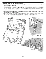
INSTALL COMPONENTS TO PC BOARD
START HERE
ê
CONTINUE
ê
CONTINUE
ê
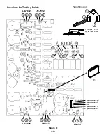
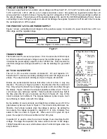
Bottom Right Corner of PC Board
Figure J
Diodes have polarity. Mount them with
the band as shown on the top legend.
Figure I
These lytics must be mounted hori-
zontal to the PC board. Bend the
leads at right angles and then insert
the leads into the PC board with the
negative (--) lead and the positive
(+) lead in the correct holes as
marked on the PC board.
START HERE
ê
Top Right Corner
of PC Board
* Leftover wire will be used in
future sections.
Band
+
r
C1 - 1000
µ
F 35V Lytic
r
C5 - 1000
µ
F 35V Lytic
(see Figure I)
r
C2 - 1000
µ
F 35V Lytic
r
C4 - 1000
µ
F 35V Lytic
(see Figure I)
r
C3 - 2200
µ
F Lytic
Mount on foil side of PC board
Note the polarity
(see Figure I)
r
D1 - 1N4001 Diode
r
D2 - 1N4001 Diode
r
D3 - 1N4001 Diode
r
D4 - 1N4001 Diode
r
D5 - 1N4001 Diode
r
D6 - 1N4001 Diode
r
D7 - 1N4001 Diode
r
D8 - 1N4001 Diode
r
D9 - 1N4001 Diode
r
D10 - 1N4001 Diode
(see Figure J)
r
L-Bracket
(see Figure B)
r
C7 - .1
µ
F Mylar (104)
(see Figure D)
r
J5 - Jumper Wire *
(see Figure F)
r
C9 - .1
µ
F (104) Mylar
(see Figure D)
r
L-Bracket
(see Figure B)
Summary of Contents for XK-550K
Page 37: ...SCHEMATIC DIAGRAM ANALOG SECTION 36 ...
Page 50: ...SCHEMATIC DIAGRAM 49 ...


