


-11-
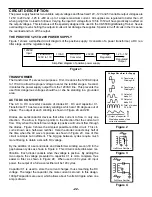
WIRE THE TRANSFORMER TO THE PC BOARD
Cut the blue, red, white and yellow wires on the transformer so they are 3” long and strip the insulation off of
the ends to expose 1/4” of bare wire. Solder the wires to the PC board starting with the top yellow wire as shown
in Figure P.
r
Yellow wire to point F on the PC board
r
Blue wire to point A on the PC board
r
Red wire to point C on the PC board
r
White wire to point E on the PC board
r
Red wire to point D on the PC board
r
Blue wire to point B on the PC board
r
Yellow wire to point G on the PC board
Yellow (F)
Blue (A)
Red (C)
White (E)
Red (D)
Blue (B)
Yellow (G)
Figure P
3”
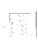
Mount U2 and U4 to the right side panel as shown in Figure
O. Insert the pins of each IC into the holes in the PC board.
Then, with the hardware shown in Figure MA, attach each
IC to the side panel. Solder the pins of the ICs to the PC
board.
r
U4 - LM7912
r
U2 - LM7812
Mount the transformer with the black wires as shown in
Figure O. Use the two 8-32 x 3/8” screws, #8 lockwashers,
and 8-32 nuts.
r
Transformer mounted
Right Side
U4
U2
7812
7912
Figure O
Black Wires
8-32 Nut
#8 Lock Washer
#8 Lock Washer
8-32 Nut
#8-32 x 3/8” Screws
Transformer
Note:
Make sure that the transformer
does not touch U4.
6-23 Nut
IC
* Silicone Grease
Mica
Side Panel
Insulator Washer
6-32 x 5/16” Screw
* Take a small amount of silicone grease from the
packet and apply it with a toothpick onto the back of
the ICs.
Figure MA
Mica
Yellow (G)
Blue (B)
Blue (A)
Red (D)
White (E)
Yellow (F)
Red (C)
Summary of Contents for XK-550K
Page 37: ...SCHEMATIC DIAGRAM ANALOG SECTION 36 ...
Page 50: ...SCHEMATIC DIAGRAM 49 ...


