


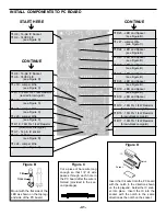


CONTINUE
ê
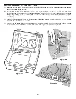
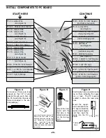
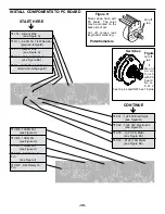
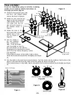
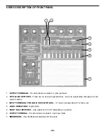
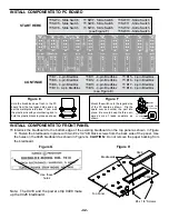
INSTALL COMPONENTS TO PC BOARD
START HERE
ê
Figure E
Mount the trim pot to the PC board as
shown below.
Figure EA
Bend the capacitors at a 45
O
angle before
soldering it to the PC board.
Figure F
Hold the bredblox down flush
to the PC board from the top
legend side and solder the
metal pins in place.
Then,
melt the plastic pins with your
soldering iron to hold the
bredblox down as shown. Re-
tin the solder tip afterwards.
Figure G
Diodes have polarity. Mount with
band in the direction shown on the
PC board.
Plastic Pins
Melt Pins
-29-
Band
r
B6 - 4 pin Bredblox
(see Figure F)
r
D16 - 1N4148 Diode
(see Figure G)
r
R14 - 100
Ω
5% 1/4W Resistor
(brown-black-brown-gold)
r
B5 - 4 pin Breadblox
(see Figure F)
r
R12 - 1K
Ω
5% 1/4W Resistor
(brown-black-red-gold)
r
R44 - 100
Ω
5% 1/4W Resistor
(brown-black-brown-gold)
r
D17 - 1N4148 Diode
(see Figure G)
r
J23 - Jumper Wire
(see Figure A)
r
R48 - 22K
Ω
5% 1/4W Resistor
(red-red-orange-gold)
r
Q1 - 2N3904 Transistor
(see Figure C)
r
R47 - 330
Ω
5% 1/4W Resistor
(orange-orange-brown-gold)
r
R46 - 330
Ω
5% 1/4W Resistor
(orange-orange-brown-gold)
r
R45 - 22K
Ω
5% 1/4W Resistor
(red-red-orange-gold)
r
J16 - Jumper Wire
r
J15 - Jumper Wire
r
J14 - Jumper Wire
(see Figure A)
r
Q2 - 2N3906 Transistor
(see Figure C)
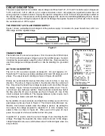
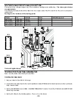
Summary of Contents for XK-550K
Page 37: ...SCHEMATIC DIAGRAM ANALOG SECTION 36 ...
Page 50: ...SCHEMATIC DIAGRAM 49 ...