-16-
Cause and Effect Matrix - continued
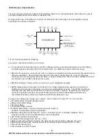
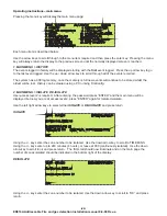
There are 3 Auxiliary relays located on the ED816A Input / Output module, each with 2 sets of voltage free
contacts. (Note the ED816A has 1 set of voltage free contacts per aux relay.)
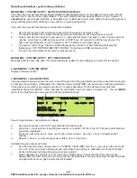
There are 3 monitored sounders on the ED816A Input / Output module. SNDR1 is the dedicated fire/gas alarm
which is operated in failsafe mode and also via the HardWare Fire Detection circuit. The HWFD circuit will
continue to give alarms, from Discovery detectors and EDL gas detectors, in the event of communication failure
between panel and loop devices, provided the loop voltage is still correct. Therefore SNDR1 should be the first
choice and should always be used with at least one sounder located in a manned area.
Sounders 2 and 3 are configurable via FireConfig.
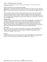
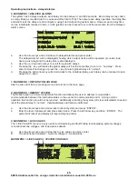
When choosing loop device in the “effect” dialogue box it is possible to select any addressable device.
However care should be taken to only select suitable devices e.g. Sounders, beacons and output
modules. The following guidelines should be observed:
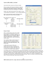
When choosing loop powered sounders / beacons as
output devices the set tone drop down box appears.
Allowing the commissioning engineer to choose which
output bits are set and hence the tone to be used.
Refer to the Apollo data sheets for individual sounder /
beacon types, below are the most common examples:
100dB loop powered sounder
0
continuous tone
1
pulsed tone
0+1
continuous tone
Intelligent base sounder
0
alternates 510hz / 610hz
1
intermittent 510hz
0+1
alternates 510hz / 610hz
Ancillary base sounder
0
continuous tone
1
not used
0+1
not used
To avoid confusion it is important to ensure all sounders use the same tones (or as similar as possible) to signal
the same condition.
Aux Relay
Sounders
Loop Device
Sounders and beacons
Output bit
Action
Output bit
Action
Output bit
Action
ED816A Addressable Fire and gas detection Installation manual 8-9-08 Rev-a


