-15-
Cause and Effect Matrix - continued
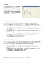
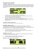
Adding Cause and Effects entries
“Cause and Effect”
“add Entry”
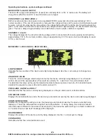
“input type”
“Device”
“Zone”
“Loop”
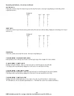
“Cause”
“Coincidence”
I/O unit Latching
I/O unit Non-Latching.
1.
Click
and then
.
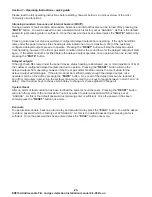
2.
Choose a name for the entry.
3.
Select the
.
is any detector, input module, zone
monitor or switch monitor on any loop.
is any of the 32 zones and also either of the
2 built in conventional zones.
is any of the loops attached to the system
only loop 1 and 2 apply for the ED816A.
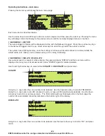
4.
Select
. Cause can be pre-alarm, alarm
or fault.
If Zone was chosen for input type an extra cause
choice becomes available.
detection is available between any 2 zones.
In the event of the 2 zones chosen both being in
the alarm condition then the effect will be actioned.
If Device was chosen for input type and the device is an I/O module, 2 extra cause choices become
available.
and
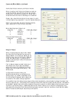
Apollo manufacture 3 main I/O modules with the following inputs:
Mains switching I/O
0
1
status of monitored switch
1
2
not used
2
3
not used
Input Output Unit
0
1
status of monitored switch
1
2
status of opto input
2
3
not used
3 Channel Input Output Unit
0
1
status of monitored switch 1
1
2
status of monitored switch 2
2
3
status of monitored switch 3
Whilst the monitored switch is open no effect will occur, once the switch closes the chosen effect takes
place.
When choosing “I/O unit Latching” the effect will remain until RESET has been pressed, any
effect can be chosen from the drop down box.
When Choosing “I/O unit Non-Latching” the effect will remain for only as long as the input is set. Only
Loop Devices can be chosen in the “Effect” drop down box. When operating a loop output device only
one non-latching cause can be assigned to it.
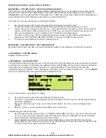
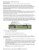
5.
Select Output type in the “effect” dialogue box, which can be Aux Relay, Sounder, Loop Device or
Delayed Output.
I/O module
input bits
FireConfig input
use
ED816A Addressable Fire and gas detection Installation manual 8-9-08 Rev-a

