-26-
Operating instructions - system voltages continued
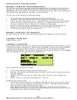
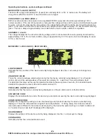
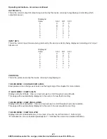
MAIN SUPPLY and AUX SUPPLY
CONV ZONE 1 and CONV ZONE 2
SOUNDER 1, 2 and 3.
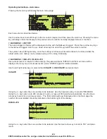
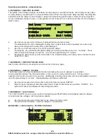
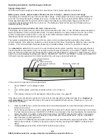
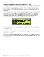
MAIN MENU > LIVE VALUES > HEAD VALUES
LOOP NUMBER
ANALOGUE VALUE
PRE ALARM, ALARM and FAULT
LIVE DEVICE CODE
CONFG DEVICE CODE
HEAD NUMBER
CONFIGURED
The main DC supply and Auxiliary DC (if used) are nominally 24V+/- 25% in normal use. The battery will
charge from either the main DC or Aux DC which ever is higher.
Both conventional zones are powered via a regulated 20VDC supply and should be approximately 18V in
normal condition. If the end of line resistor is removed this voltage will rise and the open circuit fault warning will
be given. A short circuit across the zone will see the voltage fall to almost 0V and the short circuit fault warning
given. In the alarm condition the conventional zone voltage will fall to approximately 10V and the alarm warning
given. There is a delay of approximately 6 seconds before a fault or alarm condition is signalled.
The voltage displayed is the circuit monitoring voltage which is connected with reverse polarity and should be
approximately 1.5V in the normal condition, rising to approximately 2.3 V for open circuit and dropping to nearly
0V for a short circuit.
.
Indicates the loop number of the device currently being displayed. Use the +/- arrow keys to change loop
number.
This is the current analogue value being returned by the device currently being displayed. For a Sounder
control unit, as in the example above, this would be normally 16. Less than 10 would indicate a fault.
For detectors this value will rise as the detected medium increases (smoke, heat etc.) For standard Apollo
detectors the pre-alarm value is 45 and the alarm value is 55.
Indicates whether the device currently being displayed is in the pre alarm, alarm or fault condition.
Displays the actual Apollo type code, the device type and protocol used by the device currently being displayed.
Displays the configured Apollo type code, the device type and protocol used by the device currently being
displayed. This is the code entered using the FireConfig software. If, during setup, this code was entered
incorrectly and is different to the actual code returned by the device the system will go in to fault condition and
an “incorrect device code fault” message will be displayed.
Displays the address of the device currently being displayed. Use the +/- arrow keys to change.
Indicates whether the current address is used.
10:51 05/06/08
HEAD VALUES
USER 1
LOOP NUMBER:
1
HEAD NUMBER:
20
ANALOGUE VALUE:
16
CONFIGURED:
YES
PRE ALARM:
NO
OUTPUT BITS:
0
ALARM:
NO
INPUT BITS:
0
FAULT:
NO
PROTOCOL:
XP95
LIVE DEVICE CODE:
4
SNDR CTRL UNIT
XP95
CONFG DEVICE CODE:
4
SNDR CTRL UNIT
XP95
ED816A Addressable Fire and gas detection Installation manual 8-9-08 Rev-a


