-25-
Operating instructions - delayed alarms
6. MAIN MENU > DELAYED ALARMS
7. MAIN MENU > RETURN TO MAIN PAGE
8. MAIN MENU > REBOOT SYSTEM
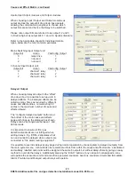
9. MAIN MENU > LIVE VALUES
MAIN MENU > LIVE VALUES > SYSTEM VOLTAGES
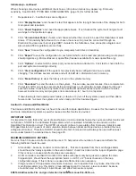
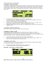
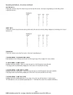
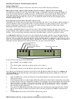
The system has 8 delayed outputs, each delay can be between 1 and 600 seconds. Each delay can be called
as many times as required (up to a cause and effect limit of 50). The output each delay operates, the delay time
and what starts the delay are all configured using FireConfig during system setup. However each delay time
can be individually reduced to zero, or all 8 (global) can be reduced to zero at the same time from the Delayed
alarms menu.
a.
Use the arrow keys and scroll down to delayed alarms and press enter.
The delayed alarm1 will be displayed showing which output device will be operated (sounder, loop
device, aux relay) and the delay time is also displayed.
b
Use the up / down arrow keys to scroll through all 8 delays.
c.
Pressing the - key will reduce the global delay (all 8 at the same time) to zero i.e. “no delay”. Press
enter to store this change or press the + key to return global delays to “normal”.
d.
Pressing the right arrow key will scroll across to the individual delay, each delay can be reduced to zero
using the +/- keys.
Has the same function as pressing menu and returns to the main page.
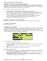
The Reboot option is a more fundamental function and allows the user to attempt to re-establish
communications between the internal modules in the event of a communications error. During normal
operation this function should not be required. Additionally rebooting the system will clear all isolated zones and
reset the global delay to “normal”. Individual delays will remain unaffected.
a.
Use the arrow keys and scroll across to reboot system and press “ENTER”.
b
Enter the level 2 password and press enter twice. Press the left arrow key and then “ENTER”. The
system will reboot and display all responding loop cards.
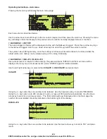
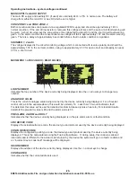
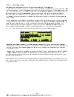
The “LIVE VALUES” menu is a very useful commissioning and fault finding tool displaying system voltages,
conventional zone voltages, and loop devices details.
a.
Use the arrow keys and scroll across to Live values and press enter.
B.
Two options are available 1. System voltages, 2. Head values.
10:51 05/06/08
DELAYED ALARM
USER 1
SHOWING DELAYED ALARM
1
SOUNDER 2
DELAY TIME 120S
GLOBAL DELAY - NORMAL
DELAY 1 - NORMAL
10:51 05/06/08
LIVE VOLTAGES
USER 1
MAIN SUPPLY: 27.5V
SOUNDER 1:
1.4V
AUX SUPPLY:
0V
SOUNDER 2:
1.4V
BATT SUPPLY: 26.9V
SOUNDER 3:
1.4V
CONV ZONE 1: 18.1V
CONV ZONE 2:
18.3V
ED816A Addressable Fire and gas detection Installation manual 8-9-08 Rev-a


