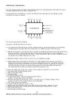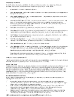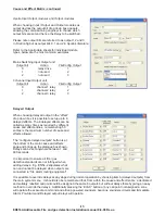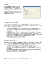
Section 3 - Control unit installation
GENERAL
WARNING: Please read this section completely before commencing installation.
The panel must be located in a clean, dry position at least 2 metres away from any radio transmitting equipment
e.g Pager systems.
NOTE
When changing any plug-in cards or loop devices, observe anti-static precautions. Ensure that all power is
removed and the system is switched off. Failure to do so may result in damage to the cards or panel.
The panel
be switched off before removing or replacing any card or module. Failure to observe this may
cause damage to the printed circuit boards.
Each loop card has an ID, set via the dip switches mounted on each loop card. No two loop card should have
the same ID.
FireConfig.exe must be used for initial system setup.
The Mains supply should be installed in accordance with the current edition of the IEE wiring regulations.
Connection to the mains supply must be via an isolating protective device (e.g. an isolating fuse) reserved
solely for the fire alarm system. It should be insured that all isolating switches, circuit breakers etc., connected
to the system should be labelled “FIRE ALARM DO NOT SWITCH OFF”.
Correct earthing is vital for trouble free operation. The earth connection should be as short as possible, using
4mm square conductors, connected directly to a good quality earth. The earth should not be routed via radio
transmitting devices or other electrical equipment.
All cables entering the control unit should be screened and ferrite sleeves, supplied with the control unit, should
be used. All screens should be terminated at the cable gland. Only metal, EMC shielding cable glands should
be used. Screens should be continuous and have continuity along the entire length of the cable. Only connect
the screen to earth at one end thus avoiding earth loops. All unscreened conductors should be kept as short as
possible and the ferrite ring should be as close to the cable gland as possible. Wrap each conductor around the
ferrite at least twice. Any communication faults experienced are likely to be caused by poor EMC shielding
practices. Repeater cable screens should never be connected to earth, always use the terminals provided.
MUST
LOOP OUT
LOOP IN
SCREEN CONNECTED
TO METAL CABLE GLAND
ENSURE GOOD
CONNECTION BETWEEN
GLAND AND ENCLOSURE
SHORT CIRCUIT ISOLATORS ARE
ALWAYS THE FIRST AND LAST
DEVICE ON A LOOP AND SHOULD
ALWAYS BE USED AT ZONE
BOUNDARIES.
ISOLATOR
ISOLATOR
ISOLATOR
CONDUCTORS WRAPPED
AROUND FERRITE CORE
ISOLATOR
ZONE 1
ZONE 32
ZONE 2
SCREEN NOT EARTHED
AT THIS END
-9-
ED816A Addressable Fire and gas detection Installation manual 8-9-08 Rev-a

