76
A
Leakage Current Tester 92-4A, -4D, -4E, -4G
BASIC TEST MODES
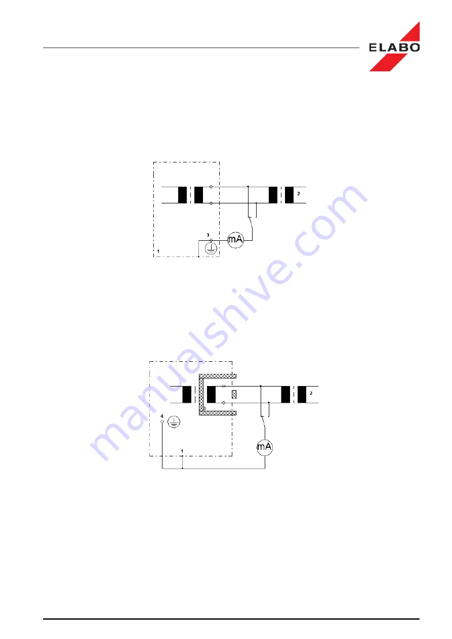
1. touchable metal parts
2. Mains
3. PE-connection
1. touchable metal parts
2. Mains
3. protective insulation
4. PE-connection
VI.iii Basic test modes according EN 60335, IEC 60335
A detailed description of the prerequisites for the measuring contains the
EN-standard.
Measurement circuits according EN 60990-1 Fig. 4
Circuit diagram:
Illustr. VI.1: Wiring for leakage current measurement for Class I test
objects (measurement mode RMS).
PE-conductor directly connected.
A1 - Measuring of the leakage current between "l" and "pe".
A2 - Measuring of the leakage current between "n" and "pe".
Illustr. VI.2: Wiring for leakage current measurement for Class II test
objects (measurement mode peak value).
A1 - Measuring of the leakage current between "l" and "vi".
A2 - Measuring of the leakage current between "n" and "vi".


