background image

2


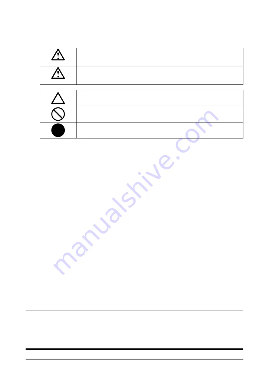
SAFETY SYMBOLS

This manual and this product use the safety symbols below. They denote critical information. Please 
read them carefully.

WARNING

Failure to abide by the information in a WARNING may result in serious injury and can be 
life threatening.

CAUTION

Failure to abide by the information in a CAUTION may result in moderate injury and/or 
property or product damage.

Indicates an attention to be required.

Indicates a prohibited action. 

Indicates a mandatory action that must be followed.

No part of this manual may be reproduced, stored in a retrieval system, or transmitted, in any form or by 
any means, electronic, mechanical, or otherwise, without the prior written permission of EIZO Corporation.

EIZO Corporation is under no obligation to hold any submitted material or information confidential unless 

prior arrangements are made pursuant to EIZO Corporation’s receipt of said information. Although every 
effort has been made to ensure that this manual provides up-to-date information, please note that EIZO 

monitor specifications are subject to change without notice.

Summary of Contents for MDF4601WT

Page 1: ...self with safe and effective usage Please retain this manual for future reference For monitor adjustment and settings refer to the User s Manual For the latest product information including the Setup...

Page 2: ...ction Indicates a mandatory action that must be followed No part of this manual may be reproduced stored in a retrieval system or transmitted in any form or by any means electronic mechanical or other...

Page 3: ...cilities etc To ensure personal safety and proper maintenance please read carefully this section and the caution statements on the monitor Location of the Caution Statements WARNING If the unit begins...

Page 4: ...nstall the monitor so that users are unable to touch the power input terminal on the rear of the monitor Touching the power input terminal may result in electric shock Apply insulation protection to t...

Page 5: ...pull Tugging on the wiring may damage it and may result in fire or electric shock Handle the power cord with care Do not place the cord underneath the unit or other heavy objects Do not pull on or tie...

Page 6: ...nitor or place any heavy objects on it Doing so may cause a person to fall or the glass to be damaged resulting in personal injury In addition the product may also malfunction Do not block the ventila...

Page 7: ...g the Screen 20 2 4 Turning Power Off 22 Chapter 3 Touch Panel Settings 23 3 1 Types of Touch Panel Drivers 23 3 2 Using Windows Standard Driver 23 3 3 Using DMT DD 26 3 4 Enabling or Disabling Touch...

Page 8: ...is manual Stylus touch pen AAA alkaline battery for stylus x 1 Rubber tip for stylus x 3 Stylus holder Cleaning cloth 1 2 Controls and Functions Front view Rear view 1 2 4 3 1 ECDIS Indicator When the...

Page 9: ...nds with touch panel operation enabled 7 button Displays the Adjustment menu or cancels adjustment setting 8 button Displays the signal name that is currently input or determines an item of the Adjust...

Page 10: ...k cable to this port to control a monitor via Ethernet a b a Link LED Green Network connection is established When turned off Network connection is not established b Status LED Blinking orange Data co...

Page 11: ...xamples Installation example 1 Horizontal Installation example 2 Vertical Attention When installing the monitor vertically place it so that the cable connectors are located on the lower side Note The...

Page 12: ...there is sufficient space around the air intake area so that air can circulate 4 Connector Do not subject the cable to any excessive load Note that load on the cable may damage the connector 5 Buzzer...

Page 13: ...ir flow Air intake area side 470 1336 433 433 50 41 Air exhaust area cooling fan side 1336 185 116 116 185 50 41 41 50 Unit mm Dimensions Ensure that no objects are placed within 60 mm of the ventilat...

Page 14: ...to form as a result of air from an air conditioner or fluctuating temperatures Where water droplets may fall from an air conditioner installed above the monitor Near the source of a magnetic field hea...

Page 15: ...apter 2 Installation Connection Outline Dimensions 400 800 200 200 1021 575 7 1336 890 157 5 157 5 157 2 157 2 91 41 Display area Mounting holes M8 Depth 15 mm Thread pitch 1 25 mm 10 holes Unit mm En...

Page 16: ...ighten the screw of the connector to secure the coupling 1 Connect a signal cable Connecting a single PC Connection example VGA D Sub DVI DVI 1 Analog connection D Sub cable DVI cable Connect one of t...

Page 17: ...mmunication cable Prepare and connect a cable required for controlling the monitor RS232C Ethernet RS485 LAN cable category 3 or higher Network Ethernet connection RS232C cable Connected to the right...

Page 18: ...complete Note When both of the power supplies are connected AC power is used Using the DC power terminal block 1 Disconnect the terminal block Terminal block 2 Connect the electrical wires to the term...

Page 19: ...ower connector 1 Remove the insulation cover from the AC power connector 2 Connect the power cord to the AC power connector Securely fix the power plug 3 Connect the power cord to the power outlet Pow...

Page 20: ...o ON by factory default lights up green when the switch is ON On Off 2 Press to turn on the monitor The monitor operation buttons light up green is blue Calibration of the touch panel automatically st...

Page 21: ...he bottom right of the screen 2 Press to switch signals 3 Press to apply the change DVI 1 DVI 2 RGB 2 VGA CVBS Autoadjust If an image does not appear even after switching input signals refer to 4 1 No...

Page 22: ...Off 1 Hold down the button for five seconds or more The progress bar is shown on the screen then the power is turned off Control buttons other than go off Attention To completely shut off the power di...

Page 23: ...to the following procedure You do not need to install the driver 1 Connecting a USB cable Make sure the USB cable has been connected between the monitor and PC see page 17 2 Setting up the sensitivity...

Page 24: ...message displayed on screen 4 Touch the screen with your finger The touched screen is recognized as a touch screen 5 Press Enter on the keyboard The Tablet PC Settings window reappears 6 Click Calibr...

Page 25: ...ows Control Panel The method for opening the Control Panel differs depending on the OS see page 23 2 Click Hardware and Sound Pen and Touch Pen and Touch window appears 3 Configure the touch panel ope...

Page 26: ...el For details refer to the TPOffset User s Manual on the CD ROM Attention When you have changed the installation location and angle of the monitor be sure to execute TPOffset 4 Setting the operation...

Page 27: ...s When 15 minutes have elapsed after that the power is automatically turned off In standby mode when the touch panel is touched with the pen tip for approximately one second the power is turned on The...

Page 28: ...cise care that you do not touch the cap while using the stylus The touch panel operations will be disabled if you touch the cap while using the stylus Handle the pen tip with care since it is fragile...

Page 29: ...points Do not bring magnetic storage media and electronic equipment closer to the stylus holder Otherwise magnetic force may hamper normal operations Do not drag the stylus holder on the monitor Doing...

Page 30: ...ge does not appear switch the input signal page 21 2 The message below appears This message appears when the signal is not input correctly even when the monitor is functioning correctly This message a...

Page 31: ...y not work correctly if a conversion adapter is used Turn the monitor off and on Hold down for two seconds or more to perform touch panel sensitivity adjustment Do not touch the touch panel until the...

Page 32: ...Hold down for two seconds or more to perform touch panel sensitivity adjustment Do not touch the touch panel until the Don t touch the panel Calibrating message disappears from the screen Perform tou...

Page 33: ...8 60 Hz 75 Hz 1152 864 75 Hz 1280 720 60 Hz 60 Hz 1280 960 60 Hz 60 Hz 1280 1024 60 Hz 75 Hz 1680 1050 60 Hz 60 Hz 1920 1080 1 60 Hz 60 Hz 1 Recommended resolution For video input CVBS Signal Format N...

Page 34: ...r Monitor Connector Model Terminal Block Model PHOENIX CONTACT CC 2 5 8 GF 5 08 FKCN 2 5 8 STF 5 08 Pin configuration Pin No Signal Pin No Signal 1 TX A output 5 RX A input 2 TX B output 6 RX B input...

Page 35: ...al 1 Tx 5 2 Tx 6 Rx 3 Rx 7 4 8 OSD port Connector 1 2 3 4 5 6 Manufacturer Monitor Connector Model Terminal Block Model PHOENIX CONTACT CC 2 5 6 GF 5 08 FKCN 2 5 6 STF 5 08 Pin configuration Pin No Si...

Page 36: ...14 5V Power C5 15 Ground return for 5V Hsync and Vsync DVI 2 RGB 2 DVI I connector Connector Pin configuration Pin No Signal Pin No Signal 1 T M D S Data 2 16 Hot Plug Detect 2 T M D S Data 2 17 T M...

Page 37: ...ation Pin No Signal Pin No Signal 1 Red Video 9 2 Green Video 10 Ground 3 Blue Video 11 Ground 4 Ground 12 Data SDA 5 13 H Sync 6 Red Video Ground 14 V Sync 7 Green Video Ground 15 Clock SCL 8 Blue Vi...

Page 38: ...AC power cord and DC power terminal block 2 Remove the fuse holder Hold down the tip of the fuse holder using a flat head screwdriver and rotate it counterclockwise 3 Attach a new fuse to the fuse hol...

Page 39: ...terminal block 2 Remove the fan cover and fan holder Fan holder Screw M3 x 8 four pcs Distribution cable Fan cover Fan 1 Remove the screws four pcs that secure the cover Use a box end wrench with 3 mm...

Page 40: ...o remove the screws 2 Remove the fan 4 Install a new fan in the fan holder Attention Handle the fan with care Dropping or subjecting the fan to physical shocks may damage it Pay attention to the orien...

Page 41: ...tep 2 page 39 Note After replacement perform the following procedure to check the operation 1 Check that the fan is rotating 2 Confirm that the Fan Error message is not displayed on the screen Periodi...

Page 42: ...ved 924 8566 153 153 Shimokashiwano Hakusan Ishikawa 924 8566 Japan 8 5B Helmut Grashoff Strasse 18 41179 M nchengladbach Germany http www eizoglobal com http www eizo co jp 1st Edition September 2017...

Reviews: