7
Chapter 1 Introduction
1-2. Controls and Functions
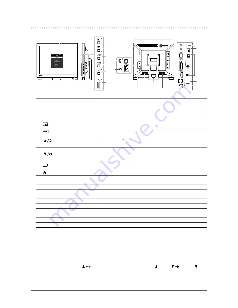
Setting menu
*1
1
11
12
13
8
9
10
14
15
17
18
2
3
4
5
6
7
16
1. Power indicator
Indicates the monitor’s operation status.
Blue:
Screen display
Orange:
Power saving mode
OFF:
Main power off / Power off
2.
button
Switches the touch panel enable and disable modes, or calibrates the
touch sensitivity (
page 9
).
3.
button
Switches input signals for display (
page 9
).
4.
button
*2
Provides an item selection and function adjustment or setting option while
the Setting menu is displayed, and displays the brightness adjustment
screen (
page 10
).
5.
button
*2
Provides an item selection and function adjustment or setting option while
the Setting menu is displayed, and displays the volume control screen
(
page 10
).
6.
button
Displays the Setting menu, determines an adjustment item of each menu,
and saves values adjusted (
page 14
).
7. button
Turns the power on or off.
8. Main power switch
Turns the main power on or off.
| : ON, ○: OFF
9. Power connector
Connects the power cord.
10. Touch pen holder attachment
hole
*3
Used to attach a touch pen holder.
11. Security lock slot
Complies with Kensington’s MicroSaver security system.
12. Speaker
Outputs audio source.
13. Stand
(with cable holder)
Used to adjust the angle of the monitor screen.
14. Headphone jack
Connects the headphones.
15. Analog voice input connector
Outputs external voice from the monitor.
16. Input signal connector
Connect it to the PC.
Upper port: D-Sub mini 15-pin connector
Medium port: DVI-D connector
Lower port: DisplayPort connector
17. USB downstream port
Connects a peripheral USB 2.0 device.
18. USB upstream port
Connects the USB cable for using the monitor as a touch panel monitor or
for using the USB Hub function.
*1 For details on usage, see
“4-1. Basic Operation of the Setting Menu” (page 14)
.
*2 In this User’s Manual, the
button may be hereafter simply referred as , and the
button as .
*3 The touch pen holder is supplied with the touch pen (Accessories (
page 35
)). For the attachment method,
see
“1-3. Attaching the Touch Pen Holder” (page 8)
.


