background image

Proprietary Information

Thompson Technology Industries, Inc.

16 Digital Drive

Novato, CA 94949

www.thompsontec.com

Installation Manual

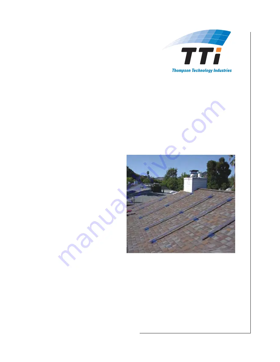
FLAT JACK® Low-Profile Roof Mount

System

Part Number 99906 Rev. D

Release 11.17.2008

NOTICE

This document is proprie-
tary, and must not be repli-
cated. It is for TTi internal 
use only and is subject to 
changes for upgrades and 
improvements.

Summary of Contents for FLAT JACK

Page 1: ...CA 94949 www thompsontec com Installation Manual FLAT JACK Low Profile Roof Mount System Part Number 99906 Rev D Release 11 17 2008 NOTICE This document is proprie tary and must not be repli cated It is for TTi internal use only and is subject to changes for upgrades and improvements ...

Page 2: ...perty of others Thompson Technology Industries Inc TTi assumes no responsibility or liability for information contained in this docu ment TTi reserves the right to make corrections modifications enhancements improvements and other changes to its products and services at any time and to discontinue any product or ser vices without notice The information contained herein is believed to be accurate a...

Page 3: ...5 2 10 Heart Pacemakers 2 5 2 11 Eye or Head Injury 2 5 2 12 Noise 2 6 2 13 Chemicals 2 6 3 FLAT JACK Overview 3 1 3 1 About This Chapter 3 1 3 2 Description 3 1 4 Site Layout Preparation 4 1 4 1 About This Chapter 4 1 4 2 Installer s Responsibilities 4 1 4 3 FLAT JACK Mounting Configurations vs Capacities 4 2 Selecting Mounting Configurations 4 2 Configuration A Description 4 2 Configuration B De...

Page 4: ...her Preparation Required 5 2 Step 1 Position FLAT JACK Base Plates 5 3 Step 2 Install Base Plates 5 4 Step 3 Install Flashing Plates 5 5 Step 4 Install Weather Guard Block and PV Module Mounting Hardware 5 6 6 Preventive Maintenance 6 1 6 1 About This Chapter 6 1 6 2 Rust 6 1 7 Obtaining Assistance 7 1 7 1 About This Chapter 7 1 7 2 Contact Information 7 1 7 3 Requesting Information 7 1 7 4 Reques...

Page 5: ...ssist you in preparing for and installing your FLAT JACK roof mount system The following other chapters are included Chapter 2 Safety Information Chapter 3 FLAT JACK Overview Chapter 4 Site Layout Preparation Chapter 5 Installation Instructions Chapter 6 Preventive Maintenance Chapter 7 Obtaining Assistance ...

Page 6: ...This page intentionally blank ...

Page 7: ...MAGE AND OR ERRONEOUS DATA IF THESE INSTRUCTIONS ARE NOT FOLLOWED 2 2 Use of Ladders DON T stand above the highest safe standing level DON T stand above the second step from the top of a stepladder or the fourth rung from the top of an extension ladder DON T climb a closed stepladder DON T climb on the back of a stepladder DON T stand or sit on a stepladder top or pail shelf DON T climb a ladder i...

Page 8: ...ot touch any energized component parts Always shut down and verify that electrical compo nents are de energized prior to performing any work on them Never perform any work on any electrical component or use any electrical tool while in contact with any water or wet surface Read understand and comply with all electrical safety instructions for all electrical tools you use Never work around or in an...

Page 9: ...awdust petroleum products solvents etc Work in a clean well ventilated area free of combusti ble materials Never overload any electrical component or tool Never use flammable liquids or gases in any confined area Do not smoke near live electrical equipment Keep your work area and surrounding environment clean at all times Should a fire occur shut off all live electrical equip ment if you can do so...

Page 10: ...y equipment for your work situation This equipment should include ANSI approved eye goggles a dust mask or respira tor non skid safety shoes hard hat and or hearing protection Live electrical components present an electrocution hazard Always shut off electrical components and verify that they are not energized prior to performing any work on them Read understand and follow all safety instructions ...

Page 11: ...etc are capable of causing serious injury Keep your hands and body well away from the working parts of any tool you use during installation Wear leather work gloves and other protective apparel or equipment depending on the work being performed and tool s being used Electrical components can generate significant heat during normal operation Never touch a hot electrical component because this can c...

Page 12: ... Z87 1 2 12 Noise Tools used during installation can also produce loud noises Prolonged exposure to noise levels above 85 dBA is hazardous to your hearing Always wear ANSI S3 19 approved ear protection when working around noisy components or tools 2 13 Chemicals Some work areas may contain hazards such as dust sawdust chemicals etc Avoid bodily contact with hazardous chemicals in any form solid li...

Page 13: ...tallation Low profile design looks good and allows ventila tion and drainage Extremely durable and corrosion resistant Can also be used to mount antennas solar ther mal devices flagpoles air conditioners etc The FLAT JACK consists of the parts shown in Dimensions are shown in Figure 3 1 A stainless steel base plate with 3 8 16 UNC mount ing stud nut lock washer and flat washer A black epoxy powder...

Page 14: ...This page intentionally blank ...

Page 15: ...ple lag screws are selected to meet applicable pull out and shear design loads Prior to installing the FLAT JACK Roof Mount system a site roof layout drawing should be created to ensure the photovoltaic PV system is structurally adequate and meets the requirements of applicable building codes IBC 2006 and ASCE 7 05 Using this installation manual the installer will have the information to show comp...

Page 16: ...gurations are recommended Configuration A This configuration is for applications where uplift loads due to wind or other design considerations seismic ice rain etc are of greatest concern See Figure 4 1 Configuration A is for uplift loads to 500 lbf 2220 N and so permits wider spacing under given conditions than the other configurations Configuration B This configuration is for applications where ...

Page 17: ... used in the lower bolt hole and another is used anywhere in the bolt slot to allow adjustability Figure 4 2 Mounting Configuration B Configuration C Description In Configuration C a fastener must be mounted in the bottom of the slot closest to the stud A second fastener must be mounted at the top of the slot to prevent slipping over time Configuration C allows all fasteners to be installed undern...

Page 18: ...n of Force 4 4 Selecting Appropriate Screws Bolts Once a layout has been developed and an uplift load on the FLAT JACK has been determined the appropriate lag screws can be selected See example calculation paragraph 4 5 NOTE These instructions describe installation into a wood substructure e g rafters For other kinds of instal lation contact TTi for assistance as instructed in Chapter 7 For mounti...

Page 19: ...staller licensed professional engineer and local building official are all responsible for understanding the assumptions and limitations of using this procedure for specifying the FLAT JACK system Method 1 for calculating the design wind load for pressures on components and cladding is generally the most applicable to PV systems on residential rooftops Example System Characteristics Wind Load Calc...

Page 20: ...applied to the layout with various spacing options and compared with FLAT JACK capacity configurations described in paragraph 4 3 With this design load Configuration C could be used with a maximum spacing of 32 Actual spacing would be determined by rafter spacing According to NDS 2005 the appropriate lag screw would then be 5 16 x 2 Confirm all layouts with your local building official Topographic...

Page 21: ...terials needed Recommended Tools Other Preparation Required 1 Position FLAT JACK Base Plates 2 Install Base Plates 3 Install Flashing Plates 4 Install Weather Guard Block and PV Module Mounting Hardware Figure 5 1 FLAT JACK Parts Included Hex nut Weather Guard aluminum spacer block P 11110 lock washer flat washer Flashing P 11122 Stud Base Plate Hex nut Weather Guard aluminum spacer block P 11110 ...

Page 22: ...Marking pen Hand Drill with bits appropriate for anchoring mate rial and size of anchoring bolts screws as determined in Chapter 4 Putty knife Not shown Chalk Line Knife for cutting shingles if needed Alternatively tin snips may be used Ratchet and 3 8 socket Extension may be required 5 4 Other Preparation Required Verify the mounting configuration you will employ following the instructions in Cha...

Page 23: ...1 Locate the positions of the FLAT JACK base plates according to your site plan They must be centered over roof rafters 2 Clear debris from the surrounding areas 3 As shown in Figure 5 2 cut notches in the upper shin gles if needed to make the base plates lie flat Figure 5 2 Shingle Notched for Base Plate ...

Page 24: ...hor bolt lag screw positions according to the anchoring configuration determined in Chapter 4 2 Drill pilot holes for lag screws through the roofing material into the rafters 3 Insert lag screws and tighten until base plate is secured flush to the roofing material Figure 5 3 Anchoring Configuration B ...

Page 25: ...ates 1 As shown in Figure 5 4 lift the shingle immediately above each base plate and insert the flashing plate as shown in Figure 5 5 with the top surface of the flashing set underneath the shingle and the notch over the base plate Figure 5 4 Lifting Shingle Figure 5 5 Inserting Flashing Plate ...

Page 26: ...Figure 5 6 Figure 5 6 Placement of Weather Guard Block 2 Place your PV module or other mounting hardware over the Weather Guard block and secure all with the washers and 3 8 UNC nut provided Hex nut Weather Guard aluminum spacer block P 11110 lock washer flat washer Flashing P 11122 Stud Base Plate P 11102 Hex nut Weather Guard aluminum spacer block P 11110 lock washer flat washer Flashing P 11122...

Page 27: ...nance 6 6 1 Preventive Maintenance 6 1 About This Chapter This chapter describes the procedures that may needed to keep your FLAT JACK product maintained 6 2 Rust If rust forms on flashing over time it should be cleaned off with a wire brush and repainted ...

Page 28: ...This page intentionally blank ...

Page 29: ...Information To request information please call and or email TTi Support 7 4 Requesting Onsite Support To request onsite support contact the TTi Support representative by telephone and email Please describe the support needed in writing making use of photographs as much as possible NOTE TTi may request assistance and or arrangement for the following transportation to and from the site for onsite su...

Page 30: ...FLAT JACK Installation Manual 7 Obtaining Assistance 7 2 7 6 Requesting Engineering Support Call or email TTi Support with a description of needed support Please indicate urgency ...

Reviews: