-46-
Mechanical Disassembly
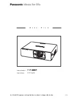
13 Lamps and ID IF boards and peripheral parts removal
1 Loosen each 2 screws on the lamp and pull it upward of.
2 Remove each 1 screw-A (T3x8) to remove the ID IF board.
A
ID IF boards
A
ID IF boards
Trigger boxes
Trigger boxes
SW905
SW906
SW904
SW903
(T3x8)
(T3x8)
(T3x8)
(T3x8)
(T3x8)
(T3x8)
LP902
LP904
LP901
LP903
Spacer
Trigger
box
(T3x12)
(T3x12)
Summary of Contents for LC-XT6
Page 192: ...192 IC Block Diagrams CXD3548 Gamma IC401 CXA7009 S H IC501 IC531 IC561 IC1501 IC1531 IC1561...
Page 193: ...193 IC Block Diagrams FA5501 PFC IC1601 IC1651 HIN202 RS232C Driver IC3801...
Page 195: ...195 IC Block Diagrams AX11005 Network IC8301 TE7783 I O Expander IC1801...
Page 196: ...196 IC Block Diagrams...
Page 204: ...SPL 8 LC XT6 Exploded Views M01 4 M01 5 Lens shift assembly M01 1 M01 3 M01 2...
Page 209: ...SPL 13 LC XT6 Exploded Views Optical filter LC CS L19 Integrator assembly S06 L11 S06...
Page 211: ...SPL 15 LC XT6 Exploded Views Relay lens OUT assembly L06 S06 S06...
Page 212: ...SPL 16 LC XT6 Exploded Views L08 L07 In the Optical unit L15 L15 L05 L22 L14 L13 L21 L09 L10...
Page 213: ...SPL 17 LC XT6 Exploded Views Optical filters assembly Mirror assembly L16 L16 L18 L17...
Page 214: ...SPL 18 LC XT6 Exploded Views Labels W09 W07 W01 W01 W06 W08 W04 W04 W04 W03 W02 W05...
Page 218: ...SPL 22 LC XT6 Mechanical Pats List...