background image

UPS MTD-XL 

UPS

 Device Description


MTD series 

29 


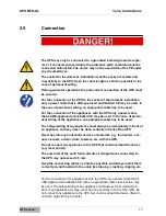
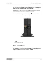
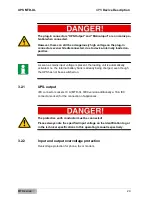
The plug-in connectors "UPS-Output" and "Mains-Input" are on mains po-
tential when connected.  

However, there can still be a dangerously high voltage on the plug-in 
connectors even while disconnected, due to device-internally loaded ca-
pacities. 


As soon as mains input voltage is present, the loading unit is automatically  
activated. I.e. the internal battery bank is already being charged, even though 
the UPS has not been switched on.  


3.2.1 

UPS-output 

IEC connector sockets 10 A (MTD-XL 3000 version additionally a 16 A IEC 
connector socket) for the connection of appliances. 


The protective earth conductor must be connected!  

Please always note the specified input voltage on the identification tag or 
in the technical specifications in this operating manual respectively. 


3.2.2 

Input and output overvoltage protection 

Overvoltage protection for phone, fax or modem. 


Summary of Contents for ACX11MST1K0000XL

Page 1: ...ible Power Supply MTD XL Operating Manual V 1 4 Article number MTD1000XL ACX11MST1K0000XL MTD1500XL ACX11MST1K5000XL MTD2000XL ACX11MST2K0000XL MTD3000XL ACX11MST3K0000XL Translation of the original O...

Page 2: ...tributed in part or in full without our consent in writing nor can it be used without authorisation for competitive purposes or given or made accessible to third parties EFFEKTA Regeltechnik GmbH Rhei...

Page 3: ...2 5 Connection 17 2 6 Operation 18 2 7 Working with Accumulators 18 2 8 Maintenance Service and Malfunctions 19 3 UPS Device Description 21 3 1 Elements on the front of the device 23 3 2 Elements on t...

Page 4: ...ackup time support time 68 11 2 Replacing the accumulators 69 11 3 Service Log 70 11 4 Service Hotline 71 11 5 Maintenance and service contracts 71 12 Technical Data 72 12 1 Specifications of the devi...

Page 5: ...During installation make sure you follow the national and local requirements for electrical installations The content of this device description may change due to technological pro gress We have trie...

Page 6: ...t all times so it is immediately available if need be 1 4 Symbols in this Manual The abbreviation UPS in this manual stands for uninterruptible power supply Read this documentation carefully and make...

Page 7: ...UPS MTD XL Introduction MTD series 7...

Page 8: ...vides a warning about hazards If accident prevention measures are not taken these dangerous situations can lead to slight or medium reversible injuries Text that is marked with ATTENTION contains very...

Page 9: ...about danger spots General warning about danger spots 1 4 2 2 Specific warning Warning about dangerous electrical voltage Warning about proper handling of accumulators 1 4 3 Instruction symbols Take...

Page 10: ...Instructions If the cross reference refers to a page figure or position number this infor mation is added at the end of the cross reference Example Fig 4 4 Pos 1 This means See position number 1 in f...

Page 11: ...as this declaration should also be given to the new owner if the device is passed on We guarantee that this device upon delivery is in a functional state and tech nically conforms to the descriptions...

Page 12: ...s done in the original packaging Incurred transport costs are generally not included in the warranty You shall bear the cost of repair and exchange and the company is not liable for damage whether dir...

Page 13: ...related to a loss of profits interruption of business loss of business information or any other losses that result from use of the device or are connected with the device whether they are based on the...

Page 14: ...n Before you take additional steps an acclimatization pe riod of at least 2 hours is to be observed Never place or operate the device in a moist environment Keep liquids away from the device The UPS m...

Page 15: ...requirements and instructions provided in this operating manual 2 2 Proper Use The UPS and its related components may only be used for purposes in accordance with its design to provide a short term su...

Page 16: ...the device Only operate the product in an appropriate and proper way and within the parameters stated in the technical data Only perform maintenance and service work that is described in the docu ment...

Page 17: ...of perma nent wiring of the appliances an appropriate cable has to be used The safeguarding of any appliance must always be immediately in front of an appliance and may never be done centrally in fron...

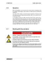
Page 18: ...r cable between the UPS and the appliance Ensure that no liquids or foreign matter enter the UPS Avoid a constant load of more than 80 on the output to protect the UPS The displayed output load should...

Page 19: ...with the power button or after discon necting the accumulator feed respectively parts of the UPS can still carry high voltages Only trained electricians with sufficient knowledge of the required safet...

Page 20: ...UPS MTD XL Safety Instructions MTD series 20 Wear personal protective equipment safety glasses gloves face shield etc The UPS may not be disassembled...

Page 21: ...ny conse quences resulting thereof The UPS system uninterruptible power supply is designed to protect sensitive electronic equipment like computers work stations electronic cash registers operations c...

Page 22: ...Depending on the field of application accumulator modules of up to a total power of maximum 100 AH can be connected to the device Please see the technical specifications for details 12 Technical Data...

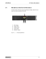
Page 23: ...on the front of the device On the front side of the device are all operating and display elements neces sary for the normal operation of the UPS 1 LCD display 2 Enter button 3 Select button 4 Alarm bu...

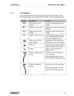
Page 24: ...equency and voltage Display output connector The UPS has two groups of out puts The display lights up when the output voltage is correct UPS status user set tings display Abbreviation for the UPS stat...

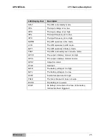
Page 25: ...he UPS operates in AVR mode bATT The UPS operates in battery mode TEST The UPS is in battery test function mode OPVH The output in battery mode is too high OPVL The output in battery mode is too low O...

Page 26: ...n pressed for at least 3 seconds To perform a battery test keep the button pressed for at least 10 seconds To turn off a pending alarm push the button for one second Selection Press the selection butt...

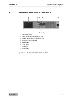
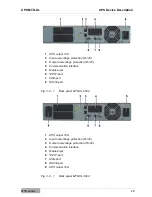
Page 27: ...3 2 Elements on the back of the device 1 UPS output 10A 2 Input overvoltage protection RJ 45 3 Output overvoltage protection RJ 45 4 Communication interface 5 Mains input 6 EPO port 7 USB port 8 RS232...

Page 28: ...n RJ 45 4 Communication interface 5 Mains input 6 EPO port 7 USB port 8 RS232 port Fig 3 2 1 Back panel MTD XL 2000 1 UPS output 10A 2 Input overvoltage protection RJ 45 3 Output overvoltage protectio...

Page 29: ...utomatically activated I e the internal battery bank is already being charged even though the UPS has not been switched on 3 2 1 UPS output IEC connector sockets 10 A MTD XL 3000 version additionally...

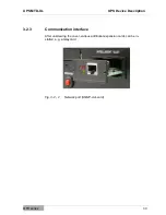
Page 30: ...D XL UPS Device Description MTD series 30 3 2 3 Communication interface After unscrewing the cover various additional expansion cards can be in stalled e g a relay card Fig 3 2 2 Network port SNMP slo...

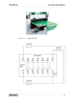
Page 31: ...UPS MTD XL UPS Device Description MTD series 31 Fig 3 2 3 Relay slot card...

Page 32: ...UPS MTD XL UPS Device Description MTD series 32 Fig 3 2 4 Relay card diagram...

Page 33: ...his operating manual respectively 3 2 5 EPO port The remote shut down port is used for turning off appliances This function can be used to turn of appliances via an external potential free contact Thi...

Page 34: ...in active for at least 20 ms to ensure proper operation 3 2 6 USB port The USB port serves to connect the UPS to a PC 3 2 7 RS232 port The RS232 port serves to connect the UPS with a PC 3 2 8 Input an...

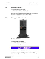
Page 35: ...brackets have to be mounted for the 19 slot 3 3 1 Setting up the UPS as a tower device Fig 3 3 1 Tower device The following steps have to be taken Rotate the display to a vertical position Position th...

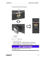
Page 36: ...3 3 2 Rotate display Press the snap lock 1 Pull the control panel 1 carefully forward and from the housing Rotate the display 90 so that it fits properly for a horizontal set up Push the display into...

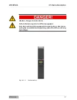
Page 37: ...r of electric shocks Perform this task only while the UPS is deengergized Even after switching off the supply with the power button or after discon necting the accumulator feed respectively parts of t...

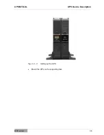
Page 38: ...UPS MTD XL UPS Device Description MTD series 38 Fig 3 3 4 Setting up the UPS Mount the UPS on the supporting feet...

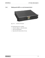
Page 39: ...series 39 3 3 2 Setting up the UPS as a rack mounted device Fig 3 3 5 Rack mounted device The following steps have to be taken Rotate the display to a horizontal position Fit the mounting brackets Mou...

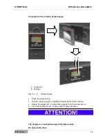
Page 40: ...3 3 2 Rotate display Press the snap lock 1 Pull the control panel 1 carefully forward and from the housing Rotate the display 90 so that it fits properly for a horizontal set up Push the display into...

Page 41: ...UPS MTD XL UPS Device Description MTD series 41...

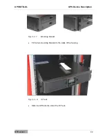
Page 42: ...UPS MTD XL UPS Device Description MTD series 42 Fig 3 3 7 Mounting bracket Fit the two mounting brackets to the sides of the housing Fig 3 3 8 19 rack Slide the UPS into the slot of the 19 rack...

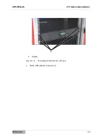
Page 43: ...UPS MTD XL UPS Device Description MTD series 43 1 Screws Fig 3 3 9 Mounting of the UPS in a 19 rack Fit the UPS with the 4 screws 1 1...

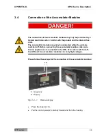
Page 44: ...r modules may only be connected while the units are switched off Before connecting the accumulator modules make sure that no appliances are connected to the UPS Even when switched off the UPS and the...

Page 45: ...UPS MTD XL UPS Device Description MTD series 45 The display is connected through a flat ribbon cable Do not pull the cable...

Page 46: ...screws front panel Remove the fastening screws 1 1 Connection cable Fig 3 4 3 Front panel Carefully fold down the front panel Connect the connection cable 1 of the UPS with the accumulator module Col...

Page 47: ...the front panel 1 of the UPS as well as of the accumulator module you find cable feedthroughs 2 that are closed in the initial state as delivered Carefully break the plastic parts of the cable feedth...

Page 48: ...ice Description MTD series 48 Fig 3 4 5 Connection of the accumulator module After the connection of the accumulator module reassemble the front panel and display on the UPS and the accumulator module...

Page 49: ...cription MTD series 49 1 Protective earth connection 2 Protective earth cable Fig 3 4 6 Earthing Connect the protective earth ports 1 of the UPS and the accumulator module with a protective earth cabl...

Page 50: ...ave to be connected with the mains power supply for ap proximately 8 hours to avoid a total discharge of the accumulators 4 2 Unpacking of the device Remove the dispatch box and packing material Keep...

Page 51: ...rference e g due to voltage fluctuation the UPS continues to provide a clean supply voltage from the UPS output without interruption During the backup mode power is provided from the battery bank 1 Ma...

Page 52: ...ower supply returns the UPS automatically turns on again supplies electricity to the appliance and controls the charging of the battery bank Prominent performance features of the MTD series are Short...

Page 53: ...specified temperature range In case of a heat build up in the installation room it must be removed through adequate powered ventilation The UPS may only be fastened on the flange base plate 6 1 Connec...

Page 54: ...UPS MTD XL UPS Installation and Connection MTD series 54 The appliances will continue to be supplied with power for the duration of the backup time...

Page 55: ...0 3000 3 0 75 mm2 for type 1000 1500 1 5mm for type 2000 3000 4 Load 1 5 Load 2 Fig 6 1 1 Connection of UPS and appliances MTD series 1000 1500 2000 3000 S 10 A 16 A 1 0 75 mm2 1 5 mm 6 2 UPS communic...

Page 56: ...PE The communication port is electrically absolutely isolated The UPS can also be forced into immediate shut down during backup mode via the RS232 interface This is triggered by a permanent 12 V sign...

Page 57: ...onnect the appliance s with the UPS Make sure that all appliances are switched off 6 3 1 Configuration of the remote shut down Conductor function Size of connecting wire Recommended wire size EPO 4 0...

Page 58: ...already be established for UPS devices with permanent wiring Due to the extensive protective functions the UPS system performs in re lation to the appliance s the UPS operates fully automatically The...

Page 59: ...and connected to the mains power supply and appliances The display shows the message STbY 7 1 2 UPS settings Please take note of the following before you make any changes to the basic settings Wrong...

Page 60: ...f mains power supply after automatic shut down in battery mode 000 deactivated 001 activated GF ECO MODE Energy saving mode Automatic shut down in battery mode at low output load 000 deactivated 001 a...

Page 61: ...figure the segment groups follow these steps Press the Enter button for 3 seconds The UPS switches into settings mode Select either LS1 or LS2 with the Select button Press the Enter button for one sec...

Page 62: ...Enter button for three seconds or the ON OFF button for 0 5 seconds to exit the settings menu 7 1 6 Green mode ECO MODE The ECO MODE energy saving mode means that the UPS turns off the outputs in bat...

Page 63: ...L Operation MTD series 63 7 1 7 Communication For the exchange of data between the UPS and a superior system the respec tive software packages are required Please see chapter Software for the range of...

Page 64: ...missioning these steps have to be followed Connect the external battery module with the UPS Connect the UPS with the enclosed connection cable to the mains power supply Adjust the necessary settings o...

Page 65: ...ppliances at the output Keep the maximum load capacity of the UPS in mind Continuous alarm and red display UPS internal error Please contact your dealer The UPS cannot be turned on The fuse has been t...

Page 66: ...If the fault indicator you registered cannot be found in this table please contact out service centre and provide the following information 1 Model number serial number 2 Date on which the issue occur...

Page 67: ...a com The following basic functions are supported by all software packages Detecting and displaying the UPS s power supply status Display of the UPS output status Detecting and displaying the charging...

Page 68: ...ce that is no longer the case the accumulators have to be replaced 11 1 Measuring the backup time support time Before you begin this procedure please make sure to save all open data Furthermore inform...

Page 69: ...you begin with this procedure Complete the tasks in the specified sequence You must use safety tools Before you begin with the task make sure the UPS is switched off and disconnected from the mains po...

Page 70: ...UPS MTD XL Maintenance and Service MTD series 70 11 3 Service Log Please always enter all maintenance and service work conducted on the UPS into the service log Date Performed tasks Performed by...

Page 71: ...ance and service contracts EFFEKTA Regeltechnik GmbH offers the related maintenance services to en sure the highest possible reliability and availability of the UPS system In addi tion we offer mainte...

Page 72: ...ges battery mode 5 Frequency 50 Hz or 60 Hz Voltage type sine wave Overload Normal operating mode 110 0 8 shut down appliances after 3 minutes 150 0 10 shut down appliances after 200 ms Battery mode 1...

Page 73: ...ustic signal in 4 seconds intervals Low battery status Acoustic signal every second Fault mode continuous signal Overload Acoustic signal every second Replace batteries Acoustic signal every second 12...

Page 74: ...tronics MTD XL MTD1000XL ACX11MST1K0000XL MTD1500XL ACX11MST1K5000XL MTD2000XL ACX11MST2K0000XL MTD3000XL ACX11MST3K0000XL X 1 x Operating Manual Printed Operating Manual English X Software package Po...

Page 75: ...mber Relay slot card ZOC AS400 SNMP mini slot card CE cs121 SL Bdget 12 3 Wearing parts list The following list of components related to regular wear and are therefore not subject to the warranty of t...

Page 76: ...with the following EU regulations and harmo nized standards EC guidelines LVD 2006 95 EC EMC 2004 108 EC Harmonised standards EN 62040 1 1 2003 EN 62040 2 2006 An EC conformity declaration for any pro...

Page 77: ...UPS MTD XL MTD series 77 EFFEKTA Regeltechnik GmbH Rheinwaldstra e 34 D 78628 Rottweil...

Reviews: