


en
5
PRODUCT IDENTIFICATION
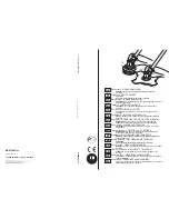
Brush Cutter Components (Fig. 1)
1 - Allen
key
2 - Combination
Wrench
3 - Locking
Pin
4 - Simple Harness (only T model)
5 - Bevel
Gear
6 - Cutting Attachment Guard
7 - Trimmer
Head
8 - Fuel
Tank
Cap
9 - Purge Bulb
10 - Carburetor Adjustment Screw
11 - Muffl er Cover
12 - Spark Plug
13 - Air Filter Cover
14 - Starter Handle
15 - Choke Lever
16 - Throttle Trigger Lockout
17 - Switch
18 - Throttle Trigger
19 - Harness Attachment Point
20 - Loop handle (TR)-(S) / Bike handle (T)
21 - Shaft
SAFETY
- This symbol indicates Warning,
and Caution.
- Your manual contains special
messages to bring attention
to potential safety concerns,
machine damage as well as
helpful operating and servicing
information. PLEASE READ
ALL THE INFORMATION
CAREFULLY TO AVOID INJURY
AND MACHINE DAMAGE.
- Wear eye, hearing and head
protection when operating this
equipment.
-
Wear non-slip, heavy-duty
protective gloves when handling
the brush cutter and blades.
- Wear safety strong shoes or
boots having skid-proof sole and
anti-piercing insert.
- Be aware that objects can be
thrown.
- Keep bystanders away 50 ft (15
m).
- Do not use the brushcutter with
the wood cutting blade.
- On machines with a bent drive
shaft (TR) it is not possible to fi t
blades, only line heads.
-
WARNING
– The surface can be
hot.
Understanding Safety Symbols