Assist3 Software
Configuring Markers
Pressing the physical A/C button on the left-hand side of the case, while the instrument is
collecting data, adds a series of sequentially numbered vertical lines to the Bx and Bz traces. For
example, if the inspector was inspecting a circumferential weld marked up in clock positions
running from 1 to 12 o’clock, 12 being top dead centre, the data could be marked up accordingly.
When the probe passes over one of the clock marks, the operator would press the A/C key to
mark the region of data corresponding to the marked position. The exact sequence of numbers
is configured in the Marker Setup dialogue box, found in Home/Markers.
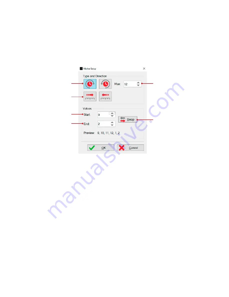
Figure 4-17
Marker setup dialogue box
The default settings assume you are starting at 1 o’clock and ending at 12 o’clock. However this
may not be the case. For example, you may be starting at 9 o’clock, scanning through 12 o’clock
and ending at 2 o’clock. In this case you would want the markers to run in the following sequence:
9, 10, 11, 12, 1, 2. For this configuration you would require the following settings:
1.
The numbers are increasing clockwise. This should not be confused with a probe moving
in the clockwise direction.
2.
The maximum number in the sequence is 12.
3.
The sequence starts with 9.
4.
The sequence ends with 2.
5.
If the operator then wanted to reverse direction and scan from 2 o’clock, through 12 and
end at 9 o’clock, they would simply press the “Swap” button to reconfigure the markers.
6.
If the operator was inspecting a linear weld, rather than a circumferential weld, then the
numbered sequence would not repeat in a rotational manner. In this case the markers
would be configured to either increase 9, 10, 11, 12, 13, 14… Or decrease: 9, 8, 7, 6, 5…
1
6
3
4
2
5
Summary of Contents for TSC U41
Page 1: ...Getting Started with TSC U41 Modernizing Subsea ACFM User s Manual ...
Page 7: ...General Precautions and Conventions ...
Page 13: ...Chapter 1 System Overview ...
Page 27: ...Chapter 2 The Subsea Bottle ...
Page 33: ...Chapter 3 The Topside Unit ...
Page 40: ...Chapter 4 Assist3 Software ...
Page 67: ...Assist3 Software 55 Figure 4 37 Finishing the installation ...
Page 69: ...Chapter 5 Troubleshooting ...
Page 71: ...Troubleshooting 59 ...


