12
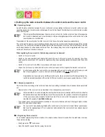
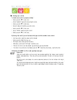
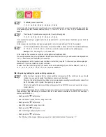
• Setting the time (minutes):
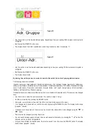
Figure 5
The LCD then displays ‘Code’ and the four-digit security code, e.g., ‘1234’.
Ö
Make a note of the security code as you may need it again later.
In addition, ‘Auto’ and ‘120’ appear on the LCD. Afterwards, the control centre begins to count down from ‘120’ in steps
of 1 second and then returns to the normal operating mode.
Ö
The control centre automatically transmits the time to the room controls once every day. This means that if
the time needs to be corrected, you only need to change it on the control centre.
This can be done as described in section 7. c).
X
X
X
X
X
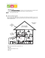
3. Installing the FHZ1000 or mounting it to a wall
• Installation
- Remove the wall holder from the back of the control centre by sliding it downwards.
- The power supply’s plug on the back of the casing is pushed from underneath into the FHZ1000.
- To install the device, open out the installation hinge on the back.
• Wall mounting
- Remove the wall holder from the back of the control centre by sliding it downwards.
- Hold the wall holder vertically on the wall with the rounded-off corners facing upwards.
- Mark the positions of the bore holes through the two slotted holes.
- Remove the wall holder and drill on the markings using a 6mm drill.
Be careful not to drill through any electricity lines, gas or water pipes!
- Insert the supplied dowels into the drill holes and mount the wall holder using the supplied screws.
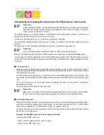
- The next step is to mount the power supply’s barrel connector in the wall holder. For this purpose, a mounting sleeve
is provided with the control centre (2 halves), which is placed around the plug and then clicked into the wall holder.
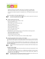
- Insert the barrel connector into one half of the mounting
sleeve, as shown in figure 6.
Figure 6
FHT 8W Heat Demand Relay
Installation and User Guide
Product Code EHC-FH06
1


