28
6. Operating the system
a) Operating structure basics
Before starting to program, please familiarise yourself with the controls, the display and the operating structure basics of
the FHZ1000:
X
X
X
X
X
1. Display and controls of the FHZ1000
Scroller
‘FUNKTION’
button
‘PROG’
button
‘
’
button
‘
w
’ button
‘MAKRO’ button ‘
x
’ button
LCD (illuminated)
The buttons below the display have the following meaning:
• ‘
x
’ button:
Go to the menu selected by the scroller
• ‘MAKRO’ button:
Confirm/save an entry
• ‘
w
’ button:
Go back to the previous menu
The battery compartment, the power supply connection for the included power supply and the mounting bracket are all
located on the back of the FHZ1000.
X
X
X
X
X
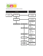
2. Operating/menu structure of the FHZ1000
In order to make programming simple and intuitive, the FHZ1000 has menu-guided programming with several layers,
similar to a mobile phone.
Figure 22
FHT 8W Heat Demand Relay
Installation and User Guide
Product Code EHC-FH06
1


