background image

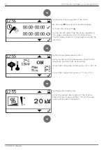
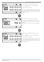
Setting the time programm of heating circuit 1.
 
By pressing  the start and stoptime appear.
 
Activate the times with 
 
During the activated time, the boiler always runs
up to the switch-off temperature without consider-
ing the Z27 contact. Outside the time, contact Z27
activates the boiler.


Setting the power of heating circuit pump 1.
 
The power range can be set between 30 - 100%.
For normal use, a setting of 30 - 70% should be
selected.
When adjusting too excessive noises can appear.


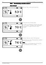
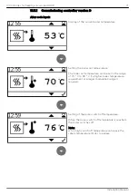
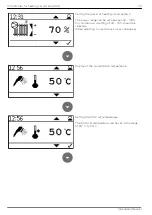
Setting the time programm of heating circuit 2.
 
By pressing  the start and stoptime appear.
 
Activate the times with 
 
During the activated time, the boiler always runs
up to the switch-off temperature without consider-
ing the Z28 contact. Outside the time, contact Z28
activates the boiler.


72

13 Controller for heating circuits and DHW

Installation Manual

Summary of Contents for Easypell

Page 1: ...Installation Manual Easypell 16 32 kW ENGLISH www easypell com 200014EN...

Page 2: ...ell 16 32 kW 200014EN 2 0 Version valid from Approved 07 2022 Christian Wohlinger Author Eco Engineering 2050 GmbH A 4133 Niederkappel Gewerbepark 1 E Mail office easypell com www easypell com by Eco...

Page 3: ...mantling the boiler door 22 7 4 3 Dismantling the boiler casing 23 7 5 Change position of flue gas fan 24 8 Performance adjustment 25 8 1 Installing the turbulators and closure plugs 25 9 Connecting u...

Page 4: ...t through and take note of the safety warnings Keep all documentation supplied with this unit in a safe place for future reference Please pass on the documentation to the new user if you decide to par...

Page 5: ...2006 95 EC Directive concerning electrical equipment for use within certain voltage limits 2001 95 EC Product Safety Guideline 2004 108 EC Directive on the approximation of laws on electromagnetic co...

Page 6: ...6 2 Intended use Installation Manual...

Page 7: ...tes a situation that could lead to death or lifethreatening injury Observe the instructions for eliminating this hazard WARNING Warning indicates a situation that could lead life threatening or seriou...

Page 8: ...Flue gas system EN 13384 1 Legislation in your country must be observed Building and fire pre vention regulations Legislation in your country must be observed Type of installation FC 42x Fireplace wi...

Page 9: ...rawn directly from the room Do not hang out washing in the central heating room Prevent dust from collecting at the combustion air intake to the pellet boiler 4 Damage due to frost and humid air The c...

Page 10: ...eter at boiler mm 130 150 Chimney diameter as per chimney calculation EN 13384 1 2 Flue gas temperature Boiler type Easypell 16 Easypell 20 Easypell 25 Easypell 32 Flue gas temperature rating 160 C Fl...

Page 11: ...ety temperature sensor The pellet boiler is equipped with a safety temperature sensor This is located on the pellet boiler If the boiler temperature exceeds 95 C then the heating system switches off E...

Page 12: ...t never bepartially or completely closed Ventila tion systems central vacuum cleaning systems extractor fans air conditioning sys tems flue gas blowers dryers or similar equipment must never be allowe...

Page 13: ...gloves for performing all work on the boiler NOTICE Damage to property Heat the pellet heating system using pellets that comply with EN ISO 17225 2 class A1 only NOTICE Damage to property Do not use t...

Page 14: ...nguishers fire protection class ABC What to do if you smell smoke Switch off the heating system Close the doors leading to living areas Ventilate the central heating room NOTICE EMERGENCY STOP SWITCH...

Page 15: ...to the data plate for the power rating of your Easypell The data plate is located on the rear side of the boiler Here you find the type designation manufacturer s serial number and year of build Key c...

Page 16: ...Flame tube 8 Anti blowback system 3 Heat exchanger 9 Burner auger 4 Boiler water 10 Electronic ignition 5 Boiler insulation 11 Combustion chamber sensor 6 Combustion chamber cover 12 Ash box 16 6 The...

Page 17: ...rner the boiler controller and the pellet hopper This will reduce the weight of the unit and make it easier to carry Tighten the hydraulic connections firmly on site and carry out a density test NOTIC...

Page 18: ...Boiler Weight Dimensions in kg Easypell 16 Easypell 20 Easypell 25 Easypell 32 Weight of boiler with casing hopper and burner 345 420 Minimum clearance dimensions required To install the heating syst...

Page 19: ...urner from wall or part of build ing 150 mm e Min room height 2050 mm Legislation in your country must be observed The indicated values must not fall below by piping or other 7 3 Casing parts Die Verk...

Page 20: ...the burner Dismantle the pellet boiler as far as necessary if site conditions require so that the unit can be brought safely into the building The complete dismantling of all components described her...

Page 21: ...7 4 1 Dismantling the burner casing and burner 1 2 3x 3 4 4x 5 6 7 Bringing the pellet boiler into the central heating room 21 Installation Manual...

Page 22: ...7 4 2 Dismantling the boiler door 22 7 Bringing the pellet boiler into the central heating room Installation Manual...

Page 23: ...7 4 3 Dismantling the boiler casing 1 4x 2 3 10x 4 5 6 7 Bringing the pellet boiler into the central heating room 23 Installation Manual...

Page 24: ...7 5 Change position of flue gas fan 1 2 3 4 24 7 Bringing the pellet boiler into the central heating room Installation Manual...

Page 25: ...exchanger tubes The heat exchanger tubes are fitted with cleaning springs that also act as turbolators On the Easypell 16 and Easypell 25 boilers some of these heat exchangers are sealed off with seal...

Page 26: ...rs 25 kW 25 kW No adjustment required 32 kW 25 kW Insert another 4 turbulators Only the adjustment of the system by an authorized Eco Engineering service techni cian can guarantee an optimal level of...

Page 27: ...TICE Insulation The flow and return pipes must be insulated according to the state of the art 1 Hydraulic schematics Always refer to the Eco Engineering hydraulic schematics when connecting up the pel...

Page 28: ...n 3 Drain connection 4 Safety valve 5 Expansion tank Two T pieces are located in the ash pan and must be mounted directly on the hydraulic connection during installation 28 9 Connecting up the hydraul...

Page 29: ...e and the fuel feeding system The boiler controller is connected to the operating device by a bus connection The operating device is located in the boiler door Visualizing of measuring values and ajdu...

Page 30: ...ty If you change microfuses ensure correct current rating 10 1 Plugs on the boiler control unit Alle Sensoren und Aktoren sind steckfertig verkabelt Die Verbindung mit der Kessel steuerung erfolgt mit...

Page 31: ...M signal for room thermostat Z26 or BR1 Z39 3 4 24 Volt PWM pump signal for output of room thermostat Z27 Z40 5 6 24 Volt PWM pump signal for output of room thermostat Z28 Z37 PF 1 2 24 Volt Accumulat...

Page 32: ...re damaged NOTICE Five safety rules Before starting work switch off lock against reclosure chech that lines and equipment dead ground and short circuit phases cover partition or screen of adjacent lin...

Page 33: ...electric shock Only a qualified person may connect the pellet boiler to the power supply Always disconnect de energize the power supply before working on the boiler 10 Fuses boiler controller 33 Insta...

Page 34: ...34 10 Fuses boiler controller Installation Manual...

Page 35: ...ity of the combustion chamber must be given The unit must be started up for the first time by an authorised Eco Engineering serv ice technician NOTICE Material Damage The allowed operation temperature...

Page 36: ...the down arrow to arrive at the next menu screen When this symbol is displayed the set value can be changed When this function is selected the value can be changed by pressing the arrow keys When thi...

Page 37: ...aning Note This message appears when the container cover has been open for longer than 20 sec onds Warning Heating full power Safety temperature sensor has released Container cover is open OFF Ignitio...

Page 38: ...Icon view Description Burner contact closed Pump active Temperarure too low Outertemperature control 38 12 Starting the pellet boiler Installation Manual...

Page 39: ...on D Accumulator heating circuit and DHW regulation for fresh water module or corrugated pipe Version E Accumulator heating circuit and DHW regulation for hot water accumulator 13 1 Code level For acc...

Page 40: ...t Z26 is determined as burner demand The boiler sensor of the heating controller must be installed into the boiler to avoid a pump function below 60 C of the boiler pump Controllable pumps are regulat...

Page 41: ...oller optional optional Heat consumers are shown symbolically and can be substituted by others NOTICE It must be ensured that the heating circuit pump only switches on from 60 C boiler temperature Oth...

Page 42: ...Wiring diagram version A The total line length of the heating circuit pumps must not exceed 100 m 42 13 Controller for heating circuits and DHW Installation Manual...

Page 43: ...range of 70 C to 90 C if a higher boiler temperature requirement or a larger modulation range is required Setting of the boiler switch off temperature When the boiler switch off temperature is reached...

Page 44: ...emperature values for the maximum and minimum boiler rating Adjustment range max rated power 10 C bis 6 C Adjustment range min power 7 C bis 25 C Setting boiler rated power Enter the desired rated out...

Page 45: ...est Conversion from constant ON OFF to pulse mode In pulse mode the boiler runs according to the start pulse until it reaches the shut off temper ature Setting operation mode Changing the operation mo...

Page 46: ...n closed PB Pellet hopper casing cover PF Accumulator sensor BS Burner starts BSK Flame return gate open Set AT Outside temperature sensor WW DHW BR1 Burner thermostat contact Z26 BR2 Burner thermosta...

Page 47: ...er than standard during the next ignition This function is automatically reset after being acti vated once and is used for faster ignition when the burner screw is empty Output test The Output Test se...

Page 48: ...Display of current boiler status 1 Current boiler temperature 2 Boiler set temperature 48 13 Controller for heating circuits and DHW Installation Manual...

Page 49: ...the boiler switches off when the end temper ature is reached DHW is controlled via sensor Z20 DHW and pump output Z16 UW Controllable DHW pumps are regulated with regard to the boiler temperature Hyd...

Page 50: ...Wiring diagram version B The total line length of the heating circuit pumps must not exceed 100 m 50 13 Controller for heating circuits and DHW Installation Manual...

Page 51: ...nge of 70 C to 90 C if a higher boiler temperature requirement or a larger modulation range is required Setting of the boiler switch off temperature When the boiler switch off temperature is reached t...

Page 52: ...n be set in the range of 30 C to 75 C Setting DHW priority During the hot water times the heating circuits are only switched on when no hot water is demanded Setting DHW hysteresis The DHW hysteresis...

Page 53: ...tside the set times Setting Outertemperature control Here you can set the temperature values for the maximum and minimum boiler rating Adjustment range max rated power 10 C bis 6 C Adjustment range mi...

Page 54: ...WM signal heating Asynchronus pump direct output 230VAC on off Heating efficient PWM 2 PWM signal solar Setting temperature unit Celsius Fahrenheit Setting operation mode Changing the operation mode 5...

Page 55: ...n closed PB Pellet hopper casing cover PF Accumulator sensor BS Burner starts BSK Flame return gate open Set AT Outside temperature sensor WW DHW BR1 Burner thermostat contact Z26 BR2 Burner thermosta...

Page 56: ...er than standard during the next ignition This function is automatically reset after being acti vated once and is used for faster ignition when the burner screw is empty Output test The Output Test se...

Page 57: ...Anzeige aktueller Kesselstatus 1 Current boiler temperature 2 Boiler set temperature 3 Current DHW temperature 4 DHW set temperature 13 Controller for heating circuits and DHW 57 Installation Manual...

Page 58: ...erful in the first code level DHW for the accumulator works via sensor input Z20 DHW and pump output Z16 UW Residual heat is dissipated via Z16 UW to the warm water boiler The pump mode cannot be sele...

Page 59: ...Wiring diagram version C The total line length of the heating circuit pumps must not exceed 100 m 13 Controller for heating circuits and DHW 59 Installation Manual...

Page 60: ...range of 70 C to 90 C if a higher boiler temperature requirement or a larger modulation range is required Setting of the boiler switch off temperature When the boiler switch off temperature is reached...

Page 61: ...ng circuit pump 1 The power range can be set between 30 100 For normal use a setting of 30 70 should be selected When adjusting too excessive noises can appear Setting the time programm of heating cir...

Page 62: ...toptime appear Activate the times with During the activated time the boiler always runs up to the switch off temperature without consider ing the Z28 contact Outside the time contact Z28 activates the...

Page 63: ...n be set in the range of 30 C to 75 C Setting DHW priority During the hot water times the heating circuits are only switched on when no hot water is demanded Setting DHW hysteresis The DHW hysteresis...

Page 64: ...tside the set times Setting Outertemperature control Here you can set the temperature values for the maximum and minimum boiler rating Adjustment range max rated power 10 C bis 6 C Adjustment range mi...

Page 65: ...Setting temperature unit Celsius Fahrenheit Setting operation mode Changing the operation mode 13 Controller for heating circuits and DHW 65 Installation Manual...

Page 66: ...n closed PB Pellet hopper casing cover PF Accumulator sensor BS Burner starts BSK Flame return gate open Set AT Outside temperature sensor WW DHW BR1 Burner thermostat contact Z26 BR2 Burner thermosta...

Page 67: ...er than standard during the next ignition This function is automatically reset after being acti vated once and is used for faster ignition when the burner screw is empty Output test The Output Test se...

Page 68: ...us 1 Heating circuit 1 2 Heating circuit 2 3 Heating circuit 3 4 Current boiler temperature 5 Boiler set temperature 6 Current DHW temperature 7 DHW set temperature 68 13 Controller for heating circui...

Page 69: ...Z17 HK and the outputs X39 and X40 The DHW sensor Z20 is attached to the accu mulator and regulates the burner demand outside the heating period Hydraulic diagram version D TI DHW heat exchanger Fris...

Page 70: ...Wiring diagram version D The total line length of the heating circuit pumps must not exceed 100 m 70 13 Controller for heating circuits and DHW Installation Manual...

Page 71: ...range of 70 C to 90 C if a higher boiler temperature requirement or a larger modulation range is required Setting of the boiler switch off temperature When the boiler switch off temperature is reached...

Page 72: ...ng circuit pump 1 The power range can be set between 30 100 For normal use a setting of 30 70 should be selected When adjusting too excessive noises can appear Setting the time programm of heating cir...

Page 73: ...mal use a setting of 30 70 should be selected When adjusting too excessive noises can appear Display of the current DHW temperature Setting the DHW set temperature The DHW set temperature can be set i...

Page 74: ...n 5K and 20 K Setting the time programm of the DHW By pressing the start and stoptime appear Activate the times with During the activated time the boiler regulates to the values indicated by the hot w...

Page 75: ...bet set between 5 K and 20 K The boiler switches on when the difference of the set temperature is higher than adjusted Setting pump release temperature of the heating circuit The pump release tempera...

Page 76: ...rated power Enter the desired rated output of the boiler to make a more accurate setting This will improve boiler runtime and modulation Settings pumptype Z16 38 Heating efficient with or without PWM1...

Page 77: ...Setting operation mode Changing the operation mode 13 Controller for heating circuits and DHW 77 Installation Manual...

Page 78: ...n closed PB Pellet hopper casing cover PF Accumulator sensor BS Burner starts BSK Flame return gate open Set AT Outside temperature sensor WW DHW BR1 Burner thermostat contact Z26 BR2 Burner thermosta...

Page 79: ...er than standard during the next ignition This function is automatically reset after being acti vated once and is used for faster ignition when the burner screw is empty Output test The Output Test se...

Page 80: ...ly demanded accumulator set tempera ture from the boiler depending on current demand 6 Accumulator set temperature 7 eating circuit Pump on temperature 8 Current boiler temperature 9 Boiler set temper...

Page 81: ...put X39 The DHW is regulated in a warm water boiler via the sensor Z20 and the pump Z40 Z17 the DHW sensor Z20 is attached to the warm water boiler The residual heat of the boiler is loaded into the a...

Page 82: ...Wiring diagram version E The total line length of the heating circuit pumps must not exceed 100 m 82 13 Controller for heating circuits and DHW Installation Manual...

Page 83: ...range of 70 C to 90 C if a higher boiler temperature requirement or a larger modulation range is required Setting of the boiler switch off temperature When the boiler switch off temperature is reached...

Page 84: ...tside the time contact Z26 activates the boiler Setting the power of heating circuit pump 1 The power range can be set between 30 100 For normal use a setting of 30 70 should be selected When adjustin...

Page 85: ...is can be set between 5K and 20 K Setting the time programm of the DHW By pressing the start and stoptime appear Activate the times with During the activated time the boiler regulates to the values in...

Page 86: ...lator hysteresis can bet set between 5 K and 20 K The boiler switches on when the difference of the set temperature is higher than adjusted Setting pump release temperature of the heating circuit The...

Page 87: ...s 25 C Setting boiler rated power Enter the desired rated output of the boiler to make a more accurate setting This will improve boiler runtime and modulation Settings pumptype Z16 38 Heating efficien...

Page 88: ...Setting temperature unit Celsius Fahrenheit Setting operation mode Changing the operation mode 88 13 Controller for heating circuits and DHW Installation Manual...

Page 89: ...n closed PB Pellet hopper casing cover PF Accumulator sensor BS Burner starts BSK Flame return gate open Set AT Outside temperature sensor WW DHW BR1 Burner thermostat contact Z26 BR2 Burner thermosta...

Page 90: ...er than standard during the next ignition This function is automatically reset after being acti vated once and is used for faster ignition when the burner screw is empty Output test The Output Test se...

Page 91: ...d accumulator set tempera ture from the boiler depending on current demand 5 Accumulator set temperature 6 Heating circuit Pump on temperature 7 Current boiler temperature 8 Boiler set temperature 9 C...

Page 92: ...y to select the desired value and select it with the confirmation button The value can be raised or lowered by pressing the keys Confirm with 13 8 Setting the time The current time is displayed The se...

Page 93: ...C Outdoor sensor min power 8 C 7 C 25 C Outdoor sensor max power 2 C 10 C 6 C Boiler power rating 16 20 25 32 10 21 kW 20 32 kW PWM pump 70 30 100 DHW set temperature 50 C 30 C 75 C DHW hysteresis 15...

Page 94: ...B103 200005 PE215 24155 200048 200003 PE243 PE473 PE174 307621 302707 PE471 PE212 E1073 210127 PE289 PE429 PE176 PE160 307517 E1204 1 307421 PE142 307419 307427 307418 307609 307608 307561 200043 B101...

Page 95: ...005 PE2151 24155 200048 200003 PE243 PE474 PE174 309121 308921 PE472 PE213 E1073 210127 PE290 PE430 PE176 PE160 307517 E1204 1 308893 PE142 308895 307427 308897 308975 308976 308903 200045 B203 B200 B...

Page 96: ...efficiency index EEI 119 118 119 121 seasonal space heating energy efficiency in active mode son 86 84 85 86 Seasonal space heating energy efficiency s based on upper heating value 80 80 81 82 Deliver...

Page 97: ...Auxiliary power consumption at 30 of nominal heat power elmin W 26 29 33 39 Water area Water capacity l 70 108 Feed return connection inch 1 5 4 Feed return connection DN 25 32 Water resistance at 10...

Page 98: ...emp partial load C 100 F g volume rated power at f g tem kg h 39 1 44 4 51 1 60 4 F g volume partial load at f g tem kg h 9 4 13 4 18 3 25 2 F g volume rated power at AGT m h 54 7 62 2 71 5 74 4 F g v...

Page 99: ...ney calculation nominal load C 160 Required or maximum delivery pressure nominal load Pa 8 Rated heating power partial load kW 5 6 8 10 Rated thermal power partial load kW 5 35 6 50 8 57 10 56 CO2 vol...

Page 100: ...bustion Air Blower W 62 Flue gas fan W 25 Electrical Ignition W 250 Cleaning Motor W 40 Flame Return Gate W 5 Noise generation dB 43 7 3 2 Protection class IP20 Further technical data and results of t...

Page 101: ......

Page 102: ......

Page 103: ......

Page 104: ......

Reviews: