


13.5
Version D
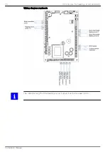
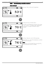
The accumulator sensor is connected to terminal Z37.
The burner demand regulates the accumulator temperature.
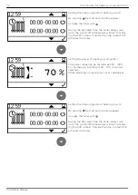
The pump output X16 (UW) and X38 (PWM) are used for the boiler controlled pump,
which is not active below 60° C. A room thermostat can be connected via inputs Z27
and Z28. This room thermostat controls the two heating circuits via pump output Z17
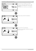
(HK) and the outputs X39 and X40. The DHW sensor (Z20) is attached to the accu-
mulator and regulates the burner demand outside the heating period.
Hydraulic diagram version D:
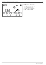
TI
DHW-heat
exchanger
Frischwasser
modul
Z21
Z16
Z38
Z20
Z37
TI
TI
TI
TI
55
50
Z27
Z28
Z17
Z39
Z17
Z40
Heat consumers are shown symbolically and can be substituted by others!
If there is more than one heating circuit, PWM pumps or the external relay box must
be used so that individual control of the pumps is possible.
13 Controller for heating circuits and DHW
69
Installation Manual
Summary of Contents for Easypell
Page 1: ...Installation Manual Easypell 16 32 kW ENGLISH www easypell com 200014EN...
Page 6: ...6 2 Intended use Installation Manual...
Page 34: ...34 10 Fuses boiler controller Installation Manual...
Page 101: ......
Page 102: ......
Page 103: ......
Page 104: ......


