background image

EAW UMX.96 Owner’s Manual

VCA Control Section

10-3

•  If the selected channel is already displayed in the master section (e.g., it is a VCA), then the displayed 

channels do not change but the VCA buttons still both light to illustrate that the faders are in channel fol-

low mode.

Once the channel is displayed, the channel follow mode follows the selected channel button push, so push-

ing select on a user bank (or if the channel is selected by select follows fader or select follows solo), that 

bucket displays. Alternately, if advancing using the channel up/down ar-

rows in the selected channel section, then the displayed bucket is the true 

channel location, and not the user bank, even if the user bank bucket was 

previously displayed.

10.2 

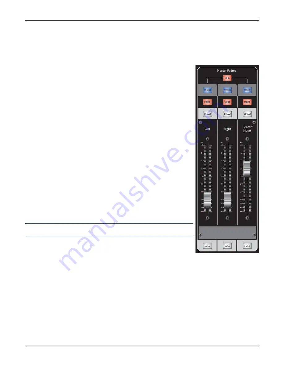
Master Faders Area

These three faders control the Main Left, Right, and Center/Mono signals.

ASSIGN Button

  — Like the 

ASSIGN

 buttons on the 48 channel faders, 

these tricolor buttons are used to assign the master faders to VCAs and 

Mute Groups. No other assignments are possible. See Sections 10.1 (VCAs) 

and 11.3 (Mute Groups) for details.

MUTE Button

 — The 

MUTE

 button lights when the corresponding main 

channel is muted. It will flash when muted by a VCA or Mute Group.

Pressing 

CTRL+MUTE

 disables the mutes of the master channels. This is 

indicated by a triple blink to off (blink/blink/blink/off) on all three of the 

master 

MUTE

 buttons. They can be re-enabled from the 

SETUP>GENERAL


screen or by 

CTRL+

Clicking on one again. This is useful to prevent acci-

dentally muting the mains and inadvertently stopping the show.

SELECT Button

 — Like the select buttons on the 48 channel faders, the 

Main 

SELECT

 button focuses the corresponding Main channel for control 

on the Selected Channel controls and the touchscreen.

Fader

 — These three touch sensitive motorized faders set the levels for 

the Left, Right, and Center/Mono System Outputs.

Note:

 Don’t overlook setting the console’s operating mode to either 

LR+Mono or LCR via the 

Setup>Operation

 screen.

Holding 

CTRL

 and touching a fader returns the fader to the bottom off 

position. This allows you to quickly reset a group of faders by holding 

CTRL

 and sliding your finger across a series of faders.

LINK button

 — The control surface 

LINK

 button links or unlinks the Left, Right, and Center/Mono faders, 

without affecting the DSP linking. This allows you to quickly offset the fader settings by turning the 

LINK


button off, change the fader settings, and then turn the 

LINK

 button back on (you can also do this by hold-

ing the 

SHIFT

 button and adjusting one of the faders). When one fader reaches the max gain value the lesser 

fader value will not go higher. 

The DSP for the Left, Right, and Center/Mono channels can be unlinked by simultaneously pressing their 

SELECT

 buttons. Simultaneously press the left and right 

SELECT

 buttons to unlink their DSP. Simultaneously 

press all three 

SELECT

 buttons to completely separate the three master faders.

Fader linking has other considerations that are related to the console’s operating mode. See Section 

12.10.1.1 under 

Setup>Operation

 for more information.

SOLO Button

 — The 

SOLO

 button routes the channel’s pre-fader or after-fader signal to the appropriate solo 

bus for monitoring. Refer to Section 6.2.1 for more info on Master LRC solo routing.

Summary of Contents for UMX.96

Page 1: ......

Page 2: ...DIGITAL LIVE CONSOLE UMX 96...

Page 3: ...2 4 Terminology Overview 2 3 2 4 1 The V Pot 2 3 2 4 2 Scribble Strips 2 4 2 4 3 Touchscreen 2 4 2 4 4 Intelligent Encoder 2 4 2 4 5 Switches 2 4 Chapter 3 Overview 3 1 3 1 The Selected Channel 3 1 3...

Page 4: ...idge 6 1 6 2 Solo Controls 6 1 6 2 1 Solo Routing 6 2 6 3 Monitor Levels 6 3 6 4 Communication 6 3 6 4 1 External Input 6 3 6 4 2 Talkback 6 4 6 4 3 Talkback Switch 6 4 Chapter 7 The Channel Section 7...

Page 5: ...e 8 13 Chapter 9 The Selected Channel 9 1 9 1 Aux Groups Area 9 2 9 2 Effects Area 9 2 9 3 Gate Compressor Area 9 3 9 4 Preamplifier Area 9 5 9 4 1 Gain V Pot 9 5 9 4 2 48V Button 9 5 9 4 3 Pad Button...

Page 6: ...Insert Post EDIT Button 12 7 12 2 4 14 Post DSP Level Meter 12 8 12 2 4 15 Direct Output Buttons 12 8 12 2 4 16 Mute Groups 12 8 12 2 4 17 VCA Groups 12 8 12 2 4 18 Mute Button 12 9 12 2 4 19 Solo Bu...

Page 7: ...7 6 Chorus 12 30 12 2 17 7 Flanger 12 31 12 2 17 8 Effects Edit Menu 12 31 12 2 18 Internal FX EQ Tab 12 32 12 2 18 1 Internal FX Equalizer Edit Menu 12 32 12 2 19 Internal FX Aux Groups Tab 12 33 12...

Page 8: ...over Editing Advanced Routing View 12 59 12 5 1 13 System Processor Output EQ 12 60 12 5 1 14 System Processor Output Delay 12 60 12 5 1 15 Polarity Invert 12 60 12 5 1 16 Output Level 12 60 12 5 1 17...

Page 9: ...12 107 12 14 2 1 Snapshot Filtering Edit Menu 12 108 12 14 3 Snap Preview Update Tab 12 108 12 14 3 1 Preview Update Edit Menu 12 109 12 15 Updating OS 12 110 Chapter 13 MM Control Software 13 1 13 1...

Page 10: ...ents TOC 8 DIGITAL LIVE CONSOLE UMX 96 w w w e a w c o m Eastern Acoustic Works One Main Street Whitinsville MA 01588 USA Tel 1 800 992 5013 T T Fax 1 800 322 8251 Part No 0013686 Rev 4 05 08 2008 LOU...

Page 11: ...AUTION Changes or modifications to this device not expressly approved by LOUD Technologies Inc could void the user s authority to operate the equipment under FCC rules ATTENTION Le pr sent appareil nu...

Page 12: ...to equipment capable of producing high sound pres sure levels use hearing protectors while the equipment is in operation Ear plugs or protectors in the ear canals or over the ears must be worn when op...

Page 13: ...Model s UMX 96 Description Digital Mixing Console Safety Directive s EN60065 2002 EMCDirective s EN55103 1 Radiated Conducted Emissions EN55103 2 Radiated Conducted Immunity 2004 108 EEC Directive Low...

Page 14: ...EAW UMX 96 Owner s Manual Safety Information 0 4 DIGITAL LIVE CONSOLE UMX 96...

Page 15: ...Channel Assign buttons and V Pots provide at a glance indication of current channel assign functions for Mute Groups VCAs Aux Groups internal effects and more The onboard 3 x 12 system processor offer...

Page 16: ...resented in bold type using their exact spelling and capitalization e g press the SELECT button Items located on the touchscreen are bold and italicized e g touch the EDIT button Touchscreen and conso...

Page 17: ...easy acces sibility during use Remember to store it for transport before closing the console s road case Caution is used for information that if not heeded may result in damage to the equipment Cautio...

Page 18: ...EAW UMX 96 Owner s Manual Introduction 1 4 DIGITAL LIVE CONSOLE UMX 96...

Page 19: ...48 mic line Inputs with digitally controlled with recall Gain 48V Phantom Power and Pad balanced inch TRS Insert Send Returns Pre DSP Insert Trim Polarity Invert HPF LPF Expander Gate Compressor 4 ba...

Page 20: ...the core and sends receives communication to from it The connections are independent so if one of these panels fails the rest continue to function Finally there is the computer It is just another inde...

Page 21: ...e output connector The left right and center mono mixes after their own set of DSP are delivered to the built in 3x12 sys tem processor These 12 outputs can be configured as crossover channels 2 way 3...

Page 22: ...coder The Intelligent Encoder uses an adaptive haptic1 rotary encoder with a weighted wheel to provide high resolution control of the parameter selected and displayed on the touchscreen This user inpu...

Page 23: ...EQ Adjust the channel dynamics section Set the level sent from this channel to any of the 24 aux group sends Set the level sent from this channel to any of the 4 internal Effects Sends Adjust the leve...

Page 24: ...be used as a pre everything direct output in addition to its more traditional role of the insert send jack In addition to the analog channel inserts the main and aux group buses have analog insert jac...

Page 25: ...tton select which aux send appears on the faders and the numbered button for that aux group flashes If a send is part of a stereo linked pair then the linked pair of buttons flashes Sends designated a...

Page 26: ...e muted as a result of a group mute flash when the mute group master is active Muting the channel via the local mute button overrides any commands from the mute group system until the local mute has b...

Page 27: ...like a traditional crossover unit and has similar controls Advanced Routing View shows the three input signals A B C and their input EQ and delay processing but each of the 12 output processors has a...

Page 28: ...can easily create your own Presets are described in Section 12 13 The snapshot system is described below with more details in Section 12 14 3 11 Snapshot Store and Recall A snapshot is just that a pho...

Page 29: ...ng Mono mix just the speaking mikes sent to a speaker that covers the choir Mono mix sent to speakers distributed through the choir that is used when the choir sings to a prerecord ed track When servi...

Page 30: ...tion between left and right while leaving the pan settings alone at the operator s level The other big plus for the matrix comes when you find that the mix sent to the downstage front fill system need...

Page 31: ...what you re hearing and to sort out feedback problems Create six aux mixes and set them to post fader Set the channel faders to the Unity mark Create the wedge mixes as required You can use the chann...

Page 32: ...e other Good Reason is that it makes these signals available for other pur poses in this case we ll use the matrix to develop the signal for the distributed system in the entrance lobby Use the system...

Page 33: ...g and other places where the system keyboard or numeric key pad popups appear The mouse can point to anything you can point at with your finger It mirrors the touch in Touch and Spin If you need more...

Page 34: ...K OF FIRE OR ELECTRIC SHOCK DO NOT EXPOSE THIS EQUIPMENT TO RAIN OR MOISTURE DO NOT REMOVE COVER NO USER SERVICEABLE PARTS INSIDE REFER SERVICING TO QUALIFIED PERSONNEL CAUTION AVIS RISQUE DE CHOC ELE...

Page 35: ...t this description Insert Send Insert Return Every mic line input has its own pair of TRS line level bal anced insert send return jacks The jacks are half normalled so the insert send jack can also be...

Page 36: ...turn available on inch TRS connectors See Section 12 5 for more info System Outputs 1 5 Right Left Center Mono 9 Send Return Send Return Send Return Right Left Center Mono Insert Insert Insert Aux Gro...

Page 37: ...ass thru option for communication be tween two consoles When the UMX 96 is used as a stage monitor console this input lets the FOH console access the monitor rig for talkback Talkback Output The talkb...

Page 38: ...nterfaces Expansion Connector This muti pin locking connector connects the mixer to future expansion devices 4 2 6 Additional Rear Panel Controls Fan Mode Pressing and holding this switch during power...

Page 39: ...r 7 for details 5 2 The Master Section The master section has the following components meter bridge SPL display bank select section channel assign section touchscreen utility section VCA control secti...

Page 40: ...ction contains the master faders for the VCA system These faders can also be as signed to follow the bucket containing the selected channel press and hold both VCA Select buttons or to control the 31...

Page 41: ...ed for voltage select switches They will work virtually anywhere in the world This also means that they are less sus ceptible to voltage sags or spikes providing greater electromagnetic isolation and...

Page 42: ...EAW UMX 96 Owner s Manual Control Surface Overview 5 4 DIGITAL LIVE CONSOLE UMX 96...

Page 43: ...signal that is sent to the system processor The red OL clip LEDs light when the signal reaches 2 dBFS If a solo is enabled the solo signal appears on the dedicated LR C M solo meters The solo meters...

Page 44: ...channel has key listen engaged Solo Level This V Pot controls the level of the solo bus in the headphones and the operator s monitor speakers The range is 15 dB This allows you to adjust the solo lev...

Page 45: ...vels These controls affect signals sent to the engineer s monitor system as configured in the Utility Monitor screen see Section 12 9 2 It can use both cue speakers wedges in ear monitor systems IEM o...

Page 46: ...dividual channels for Matrix LR C M and Auxes Groups the buttons enable or disable these selected channels as a whole Note The destinations for the console s talkback mic input are independent of thos...

Page 47: ...ribble strip displays the name for that channel what you d scribble on the white tape usually used on an analog console The digital version on the UMX 96 also shows the current Channel Assign setting...

Page 48: ...ing All faders on all channels default to off The Setup General option Select Follows Faders allows the select button and thus the Selected Channel and touchscreen channel control section to follow a...

Page 49: ...ign it to the Selected Channel and or to the touchscreen by enabling Select Follows Solo This configuration setting is located on the Setup General screen of the touchscreen When enabled enabling a so...

Page 50: ...EAW UMX 96 Owner s Manual The Channel Section 7 4 DIGITAL LIVE CONSOLE UMX 96...

Page 51: ...nel meter scribble strip V Pot ASSIGN MUTE SELECT buttons as well as the fader Note that this problem can also be solved using input patching which is described in Section 12 8 User banks are describe...

Page 52: ...locked meaning if you change the underlying channel bank the master banks will remain in view until you manually clear them See the Bank Hierarchy section below for more information The following Mast...

Page 53: ...n the lower line and the ASSIGN button matches the color of the lit Channel Assign button The Channel Assign buttons typically act in an exclusive manner with one lit at a time unless otherwise detail...

Page 54: ...corresponding VCA groups At the channel strip the ASSIGN button illuminates for any channel belong ing to the chosen VCA group Enabling an ASSIGN button adds the channel to the VCA group Disabling an...

Page 55: ...n out Gate Thresh old Gate gain re duction meter Flashes to indicate gate key listen in Default Gate key listen in out via the solo system Line 1 Channel name Displays threshold set ting when V Pot is...

Page 56: ...and the pad value 23 dB if enabled so the number you see is the actual amount of gain being applied to the input For Mic Line inputs 1 48 this range is between 15 dB and 70 dB without the pad and 8 d...

Page 57: ...HPF frequency The bottom line of the scribble strip displays the word HPF The V Pot LEDs indicate the relative frequency setting The V Pot button toggles through the slope values The first push interr...

Page 58: ...tereo channel and it does not light if the polarity setting of the two channels is the same Holding CTRL and pressing the INV Channel Assign button disables polarity invert on all channels 8 2 2 8 PAN...

Page 59: ...48V off on ALL channels On Off n a n a n a n a n a Line 1 Channel name Line 2 48V DELAY Channel delay time Turns Delay off on ALL channels On Off Delay time Delay value n a 0 ms n a Line 1 Channel na...

Page 60: ...lays DSP FDR or FDR When either of the pre positions is selected the bottom V Pot LED illuminates Group sends are always post fader sends the concept of pre fader does not apply Holding CTRL and press...

Page 61: ...an obvious way since it is a fairly drastic change in console operation Enabling Aux Mode changes the channel faders on both the upper and lower banks to instead control the aux send levels from the...

Page 62: ...ed as Mono Aux or Mono Stereo Group then Gain Pad is automatically selected as the V Pot control the GAIN PAD button lights and that Aux Group flashes as the selected Aux Mode fader control If Aux GRP...

Page 63: ...e of the Channel Assign section Repeat the procedure to remove the custom channel assignment Example In a monitor mixing application the lead vocal channel is on channel 24 of the bottom bank as it wi...

Page 64: ...EAW UMX 96 Owner s Manual Bank Select and Channel Assign 8 14 DIGITAL LIVE CONSOLE UMX 96...

Page 65: ...ol by the Selected Channel The Channel Select Left and Right arrow buttons located above the equalizer section in the Selected Channel allow you to move the selected channel to the next or previous ch...

Page 66: ...ere each of the V Pots will instead control the master level control for its send These are the same levels that are under control of the faders on the AUX GRP 1 24 Channel Bank The amber LEDs for the...

Page 67: ...s below the threshold are made quieter while signals above the threshold are allowed to pass through Compare this with what the gate does The Range control is replaced by a Ratio control and the Hold...

Page 68: ...e Bottom LED indicates gain reduction Release knob Varies the release speed from 50 ms to 3 seconds Sets the release time to 250 ms Release time value Hold knob Varies hold time from 0 5 seconds Not f...

Page 69: ...owering on ALL channels at once hold CTRL and press the 48V Channel Assign button 9 4 3 Pad Button The red PAD assign button enables the Selected Channel s 23 dB pad ahead of the mic preamplifier Note...

Page 70: ...m LED Ctrl Shift knob Button Ctrl Shift button Gain Preamp gain 0 to 70 dB 8 to 47 dB w Pad Stereo channels 0 to 20 dB Preamp Gain Gain value n a Ctrl n a n a V Pot LEDs show relative setting Pad 23 d...

Page 71: ...trol adjusts the cutoff frequency for the filter Frequencies below the cutoff frequency are attenuated at a rate of 12 dB octave default The slope for the HPF is adjustable by pushing the V Pot button...

Page 72: ...rts LPF Low pass filter White button In Out for filter Knob Filter frequency 400 Hz 20 kHz Default 20 kHz V Pot button Cycles through filter slopes 6 12 18 24 dB octave The display indicates slope set...

Page 73: ...ly the LR assign button is pressed the pan control works as a stereo control 9 6 1 Mute Button The mute button is a red backlit button that is lit when the channel is muted and unlit when it is passin...

Page 74: ...EAW UMX 96 Owner s Manual The Selected Channel 9 10 DIGITAL LIVE CONSOLE UMX 96...

Page 75: ...lay shows the short names for the corresponding channel This is usually a VCA group but may also be an Aux Group Master when Aux Mode is enabled see Section 8 2 3 4 or any other channel when Channel F...

Page 76: ...either of the VCA Select buttons returns the VCA faders to normal operation 31 Band Graphic EQ control is described in detail in Section 12 2 23 10 1 2 Aux Mode In aux mode the level settings of any...

Page 77: ...stopping the show SELECT Button Like the select buttons on the 48 channel faders the Main SELECT button focuses the corresponding Main channel for control on the Selected Channel controls and the tou...

Page 78: ...EAW UMX 96 Owner s Manual VCA Control Section 10 4 DIGITAL LIVE CONSOLE UMX 96...

Page 79: ...tops torque etc it meant using a different part There was no way to change this after the fact without replacing the part Digital consoles typically use multifunctional encoders to deliver rotational...

Page 80: ...d then pressing the unlit ASSIGN button for each channel that you wish to add This method is Mute Group specific it allows you to assign multiple channels to a single mute group see Section 3 9 3 From...

Page 81: ...ionship via the touchscreen by going to Setup General Screen Follows Selected Channel To use the touchscreen just touch the visual element that you wish to adjust If it is a button or switch touching...

Page 82: ...ystem processor 12 5 Smaart Smaart Live Analyzer 12 6 Effects Internal effects modules 12 7 Routing Input and Output routing 12 8 Utility Access to Talkback Monitors Tone Generator SPL Meter User Bank...

Page 83: ...secondary tabs Overview Overview of the selected channel parameters 12 2 4 Delay Channel alignment delay 12 2 5 EQ Channel four band EQ and HPF LPF related parameters 12 2 6 Dynamics Channel Expander...

Page 84: ...etup General see Section12 10 2 12 2 2 Link Button The Link Button allows linking an odd and even numbered adjacent channel pair for stereo operation After pressing the Link button a pop up dialog box...

Page 85: ...the other At the bottom is a representation of the main DSP blocks for the channel along with the Aux Groups and Internal EFX sends 12 2 4 1 Overview Edit Menu The Overview screen s edit menu has the...

Page 86: ...his function Note To disable phantom powering on ALL channels at once hold CTRL and press the 48V Channel Assign button 12 2 4 4 Pad Button The Pad button enables the Selected Channel s 23 dB pad ahea...

Page 87: ...im control The readout below the knob displays the actual trim setting 12 2 4 10 HPF IN Button The HPF IN button engages the channel s high pass filter Set the HPF frequency via the Equalizer tab 12 2...

Page 88: ...usage is the same as a VCA found in an analog console There are 16 VCA groups The 16 VCA Group buttons assign the channel to that numbered VCA Any channel can belong to more than one VCA group The act...

Page 89: ...assigned main buses depending upon the console s operating mode L R mono or LCR and channel Mix Assign see Mix Assign Buttons next In LCR mode the Pan control is a true LCR control IF the L R and CENT...

Page 90: ...tton to turn on or off the low pass filter Touching anywhere else in this area takes you to the EQ tab where you can make further adjustments to the equalizer settings For more information see the sec...

Page 91: ...in Setup General The delay dis tance is calculated using the following formula Delay_Meters 401 8 x Temp_Celsius 273 15 x Delay_Seconds Use the DELAY ON button to enable disable the channel delay This...

Page 92: ...like most equalizers of this type These ranges are as follows Low 20 Hz to 400 Hz Low Mid 100 Hz to 2 0 kHz High Mid 400 Hz to 8 0 kHz High 1 0 kHz to 20 0 kHz In Full Range mode the four bands are nu...

Page 93: ...Spectrograph toggle switch above the EQ graph Many audio signals that are encountered in the field are highly dynamic musical signals speech and even environmental noise contain significant changes in...

Page 94: ...discussion in Section 9 3 The Gate Expander has the following features Input Reduction and Output level meters These three meters show the input level output level and amount of gain reduction These t...

Page 95: ...both Linkwitz Ri ley designs with a range of 20 Hz to 20 kHz and a slope of 12 dB octave The Key In Key Out switch enables disables the key filter section bringing the filters in out of the key signal...

Page 96: ...der the output gets 1 5 dB quieter for a 1 dB below threshold change of the input signal As you can see quiet signals those below threshold get even quieter In the picture the input level is the horiz...

Page 97: ...compressor to end gain reduction once the signal drops back below the threshold GAIN control Adds makeup gain to the output of the compressor This is useful to make the apparent volume of the signal...

Page 98: ...red by all of the dynamics processors It has the following com mands Save Dynamics Preset As Saves the current dynamics settings as a preset under a user defined name Load Dynamics Preset Loads a prev...

Page 99: ...again be displayed if present Because it is a group send there is no level control or pre post indica tor just an IN button To the right are the Internal EFX sends They are always post fader thus the...

Page 100: ...e inserts The IN buttons allow enabling the inserts and for software DSP inserts the Edit buttons allow quick access to the DSP processor control screen Inserts are configured in the Routing Insert Ro...

Page 101: ...key sig nal is a mono sum of the left and right channels preventing image shift caused by unequal gain reduction in the two channels The input output metering for the Compressor is also stereo There...

Page 102: ...he entire channel settings to the clipboard Paste Pastes the clipboard delay settings to the input delay 12 2 12 Stereo Channel EQ Tab The stereo channel s Equalizer works identically to the mono anal...

Page 103: ...ned name Load Compressor Preset Loads a previously saved compressor preset Reset Compressor Resets the compressor to its default settings Copy Copies the channel s settings to the clipboard Paste Past...

Page 104: ...ttons allow enabling the inserts and for software DSP inserts the Edit buttons allow quick access to the DSP processor control screen Hardware inserts are configured in the Routing Insert Routing scre...

Page 105: ...nts Input Level Meter Mono level meter that displays the send level into the Effect processor Effect Selection A set of buttons that selects the effect for this send EQ Display and IN button Display s...

Page 106: ...plays the equalizer screen 12 2 16 1 Internal FX Edit Menu The FX channel Edit Menu has the following commands Save Channel Preset As Saves the channel s settings as a preset using a user defined name...

Page 107: ...ximately 340 meters per second 1100 feet per second This means that in one millisecond it travels 0 34 meters 110 feet As a rough idea think of 1 ms as the time it takes for sound to travel one foot T...

Page 108: ...Gate effect has all the same controls as the Reverb effect previously discussed but with the ad dition of a Gate after the reverb section This allows you to set the threshold for when the reverb effec...

Page 109: ...and equalizer for the reverb effect on and off When the EQ is on you can drag the nodes in the EQ window and adjust the parameters of the EQ Gain Frequency and Q Band 2 only or touch the EDIT EQUALIZE...

Page 110: ...des from which to choose Modes 1a and 1b apply one chorus voice 2a and 2b apply two chorus voices 3a and 3b apply three chorus voices and 4a and 4b apply four chorus voices The difference between the...

Page 111: ...nge effect by adding even more comb filtering to the signal FUNCTION PARAMETER VALUE RANGE INCREMENT DEFAULT VALUE Flange Pre Delay 0 100 ms 1 ms steps 0 ms Mode 1a 1b 2a 2b 3a 3b 4a 4b 1 Depth 0 10 m...

Page 112: ...rve generated The three band EQ is considered part of the effect DSP It is used by the library of presets to shape the post effect tone Thus the Equalizer s controls are always linked regardless of th...

Page 113: ...he figure below This is done to prevent feedback loops For further information refer to Section 12 2 8 12 2 19 1 Internal FX Aux Groups Edit Menu The internal FX channel Edit menu has the following co...

Page 114: ...on the console s mode setting In LCR mode the return is via the Pan control and the L R and Center assign buttons If only the L R assign is enabled then the pan control operates in 2 channel stereo mo...

Page 115: ...not enabled the DAC ADC pair are not part of the circuit Since this adds latency to the signal enable it only if it is going to be used Mute ON button Enables the channel mute Solo ON button Sends the...

Page 116: ...s edit menus are the same as those for the mono analog channels The 31 Band Graphic Equalizer is unique to the Aux Group channels and has its own Edit menu 12 2 21 Aux Groups EQ Tab This is the same a...

Page 117: ...ed in more detail in Section 12 6 and in the Smaart User Guide The bottom half of the screen displays the 31 band graphic EQ Touch the buttons along the bottom of the screen to assign groups of eight...

Page 118: ...information 12 2 25 Aux Groups Inserts Tab This tab allows control of the pre DSP and post DSP digital inserts Refer to Section 12 2 9 for details 12 2 26 Aux Groups Ch List Tab This tab displays a li...

Page 119: ...tton swaps the order of the Compressor EQ and Master Fader The graphic display elements exchange places for every press of the button Master Fader The master fader for the selected system output Inser...

Page 120: ...nput channels Refer to Section 12 2 7 4 for an explanation of the controls for the compressor 12 2 29 LRC RTA 31 Tab The 31 band graphic equalizer operates the same as described in the Aux Groups sect...

Page 121: ...Reset Channel List Unassigns every channel on this list Copy Copies the channel list assignments to the clipboard Paste Paste the clipboard contents to the currently displayed channel 12 2 32 LRC Lin...

Page 122: ...An overview of the 16x1 mixer with independent input sources Insert Pre EDIT button Pre DSP digital insert point Touching the EDIT button accesses the Inserts screen the same as touching the Inserts t...

Page 123: ...ys the pre fader level of the matrix 12 2 34 1 Matrix Overview Edit Menu The Matrix Overview screen s Edit menu has the following commands Save Channel Preset As Saves the matrix channel s settings as...

Page 124: ...input mixer s inputs The complete list of sources is as follows Analog 1 48 Pre DSP Pre Fader Post Fader Expansion 49 96 Pre DSP Pre Fader Post Fader Stereo 1 8 Left and Right Pre DSP Pre Fader Post...

Page 125: ...t unchanged Reset Matrix Input Levels turn off all input faders but leave input assignments and In Out status un touched Copy Copies the current matrix channel to the clipboard Paste Pastes the clipbo...

Page 126: ...ders displays the Mute Group Assign and VCA Assign for the selected VCA group VCAs can be assigned to Mute Groups like any other channel and they can be assigned to other VCAs of a higher number So VC...

Page 127: ...the source bank of the channel you wish to add remove Then simply check uncheck a channel in the Bank Channel Assignment list to add remove it from the VCA Repeat as necessary Example To assign a cha...

Page 128: ...EAW UMX 96 Owner s Manual Touchscreen Interface 12 48 DIGITAL LIVE CONSOLE UMX 96...

Page 129: ...dds to 24 A toggle switch on the Aux Group setup screen selects Aux mode or Group mode for each bus Changing the mode will prompt you for confirmation as changing the mode will reset all the channel s...

Page 130: ...rface 12 50 12 3 1 Aux Group Edit Menu The Aux Group setup screen s Edit menu has the following command Adjust Pre Post State for All Sends Accesses a dialog that allows setting the pre post state for...

Page 131: ...tting for every matrix input None of these controls are directly adjustable however they provide a clear visual overview Touching anywhere in a row takes you to the input mixer see Section 12 2 14 2 f...

Page 132: ...EAW UMX 96 Owner s Manual Touchscreen Interface 12 52 DIGITAL LIVE CONSOLE UMX 96...

Page 133: ...out puts connect via the 12 legs of the System Processor Output SPOUT to the 12 system outputs on the rear panel The system processor is only accessible and adjustable via the touch screen and the In...

Page 134: ...the input signal When the input is muted there is no signal at any of the proces sors outputs 12 5 1 5 System Processor Input Equalizer Touch the EQ button to access the equalizer screen The LED below...

Page 135: ...sing bringing the individual zones in a venue into alignment and Array processing aligning the overall components in an array The delay is not specifically designed for Box alignment aligning the comp...

Page 136: ...to the output legs 1 through 12 to their right The Input Selection for processor inputs A B and C defaults to Left Right and Center Mono respectively To change a routing Just to the right of the input...

Page 137: ...anced Routing View see the toggle switch between the B and C Input Selectors the crossover abstraction is removed and you are free to treat each of the 12 outputs as an individual frequency band that...

Page 138: ...bandpass filter LP FILTER Low pass filter forms the HF end of the bandpass filter IN Turns filter on In Out CORNER FREQ 3 dB frequency of the filter 20 Hz 20 kHz Touch and Spin FILTER TYPE Slope and c...

Page 139: ...24 dB octave Linkwitz Riley 12 24 dB octave Touch and Spin Band Edit Select Selects a band 1 of 12 for editing in the Selected Band Edit area The last four buttons selected are lit in the Band View S...

Page 140: ...both Standard and Advanced Routing Views This is done to allow the EQ to be adjusted with the corresponding X Over in view 12 5 1 14 System Processor Output Delay This works the same as the System Pro...

Page 141: ...Release Release time 50 ms to 3 seconds Ratio Compression ratio 1 1 to infinity 1 Input Meter Input level 48 dBFS to 0 dBFS Reduction Meter Gain reduction applied 30 dB to 0 dB Output Meter Output le...

Page 142: ...12 62 12 5 2 Limiters View Tab This tab displays the entire System Processor output limiters from an operational perspective Every control setting is visible as are input output and gain reduction me...

Page 143: ...he Smaart button displays the built in Smaart software for system analysis and tuning purposes It has two sub tabs along the top Smaart Live and Setup The Smaart Live tab accesses the Smaart interface...

Page 144: ...s can be useful for comparing two different microphone inputs or to analyze the response of a DSP pro cess within the console In addition to the dedicated Smaart Tab the Parametric channel EQ and RTA3...

Page 145: ...us produced by modulating the delay time of a delay line Mono Delay Mono delay with feedback Stereo Delay Mono in stereo out delay with feedback No cross coupling Ping Pong Mono in stereo out delay wi...

Page 146: ...EAW UMX 96 Owner s Manual Touchscreen Interface 12 66 DIGITAL LIVE CONSOLE UMX 96...

Page 147: ...e a connection from a hardware input to a mixer input channel Hardware inputs can be routed to multiple channels The hardware inputs are grouped into the following 24 channel groups Analog 1 24 Analog...

Page 148: ...e s output channels shown along the left side using custom names if present Touch an inter section to create a connection from a mixer output channel to a hardware output Mixer output channels can be...

Page 149: ...n to create a connection from a mixer output channel to a hardware output Mixer direct output channels can be routed to multiple hardware outputs The channels are divided into the following 24 channel...

Page 150: ...hardware layout in a rack Down arrow Moves an insert down the list so you can organize the list to match the hardware layout in a rack Once an insert has been created the name appears in the name col...

Page 151: ...has the following commands Save Insert Routing Preset As Saves the insert current routing assignments as a preset under a user defined name Load Insert Routing Preset Loads a previously saved insert...

Page 152: ...EAW UMX 96 Owner s Manual Touchscreen Interface 12 72 DIGITAL LIVE CONSOLE UMX 96...

Page 153: ...s independently routing either talkback signal to any of Aux Groups 1 24 Matrix 1 8 and the left right mono center Four master control buttons L R C M Matrix Auxes Groups are also located in the conso...

Page 154: ...istance units and is adjustable in 0 5 ms 6 6 inches steps Solo Level A knob and readout matching the setting of the control located on the control surface This control adjusts the level of any source...

Page 155: ...r Mode In this mode all outputs are fed only by their individual LRC bus Center Mono Powered Monitor Left Powered Monitor L R C M Right Powered Monitor 3 Speaker LR C M Monitor Output Mode In Ears and...

Page 156: ...e audience 12 9 3 Tone Noise Generator Tab This screen controls the internal tone noise generator You can select white noise pink noise or sine waves at 100 Hz 1 kHz 10 kHz and 440 A 440 Hz The genera...

Page 157: ...Owner s Manual Touchscreen Interface 12 77 12 9 4 SPL Meter Tab This tab allows setting up the SPL meter and record log Note The SPL Meter is currently not implemented but will be added in a future u...

Page 158: ...o columns Source Bank and User Bank The left column displays a set of buttons to choose which 24 channels from the list below to show Analog 1 24 Analog 25 48 Expansion 49 72 Expansion 73 96 Stereo 1...

Page 159: ...down Whatever was assigned to channel 24 goes away It does not matter if there were unassigned channels between channel 24 and the last assigned channel Clear Clears the current user bank destination...

Page 160: ...Analog 1 24 Analog 25 48 Expansion 49 72 Expansion 73 96 Stereo 1 8 Stereo IFX Returns 1 4 Aux Groups 1 24 Main Matrix VCA 1 16 The left two columns show all channels available for mute groups within...

Page 161: ...ou wish to remove The system removes it from the mute group Channels below it on the Assigned Channel Overview list move upwards to fill the gap The Master Group Mute buttons are located in the consol...

Page 162: ...ssign a master bank to the selected bucket Unassign a section by selecting the bucket and pressing the NONE button One other button LOCK controls the operation of the master banks When LOCK is enabled...

Page 163: ...re located in the Touch and Spin sec tion of the console between the snapshot buttons and the master mute group buttons These buttons can be assigned to mixer func tions via the User Keys tab in the U...

Page 164: ...These meters follow the assignment made for the Master Bank of Console meters A row of buttons at the top of the screen duplicates the MeterBridge assign ment switches on the control surface These bu...

Page 165: ...compensate For example if the mic pre is turned up by 5 dB on the Master the digital trim is turned down by 5 dB on the Slave Slave Compensation This button will only appear when the console is in Mas...

Page 166: ...t Outputs deliver the stereo signal The Mono output is available at the C Mono output Channels can be assigned to both Left and Right and or to Mono Mono Source Pan LR M Pan M CTR L L R R Channels ass...

Page 167: ...for LRM Mode with Link On L R M L R M L R M Default for LCR Mode 12 10 2 General Tab The General tab contains additional global setup parameters Exclusive Solo On or Off default off When enabled only...

Page 168: ...for any channel by pushing the Gain V Pot button for the channel Holding CTRL while pressing this encoder will clear Clips for all channels LED Brightness Adjusts the brightness of the LEDs so you can...

Page 169: ...t will display UNLOCKED if there is no valid clock signal present Sample Rate 44 1k 48k 88 2k or 96k default 96k 96k offers the lowest latency and best audio perfor mance so it should be used at all t...

Page 170: ...d sends MIDI note commands for mutes and continuous control lers for faders The console also responds to these same MIDI commands Snapshot Chase MTC button When enabled incoming timecode causes snapsh...

Page 171: ...Lock System Processor Setup This tab lists different components of the system processor that can be locked via a checklist Checked items will not be able to be changed once the system processor is lo...

Page 172: ...e the default channel names used throughout the console and software The short name is used for console Selected Channel read out touch screen matrix 16 x 8 view touch screen matrix input mixer touch...

Page 173: ...o the end of the list The delete key deletes the character immediately to the left of the cursor The up and down arrow keys at the bottom left move the active line up and down the screen The left and...

Page 174: ...Analog 25 48 Expansion 49 72 Expansion 73 96 Aux Groups 1 24 Matrix 1 8 VCA 1 16 Mute Groups 1 8 Internal FX Sends 1 4 Internal FX Returns 1 4 Left and Right Stereo Inputs 1 8 System Processor In A B...

Page 175: ...tiple Configurations and Shows Snapshots presets shows and console configurations are stored on the console and can be copied to an attached USB mass storage device like a thumb drive or external hard...

Page 176: ...and a third column displays a file browser and associated buttons for choosing a location to save The first column is a list of snapshots in the currently loaded show on the console It displays the s...

Page 177: ...tem in the list can be selected at one time Use the Up Arrow and the Open buttons blue to navigate through the file structure Use the New Folder button to create new folders Below the browser list are...

Page 178: ...m in the list may be selected at a time The OPEN and Up buttons respond to the item selected and its place in the file system For example if a folder is selected the OPEN button will be enabled and if...

Page 179: ...he current show will be unaffected This allows loading snapshots from multiple shows into the console which could be useful if two bands need to have both their snapshots loaded from different shows O...

Page 180: ...e using the Up Arrow and the OPEN buttons blue Create new folders with the New Folder button blue Unlike the other browsers a check box follows each displayed item These can be checked or unchecked al...

Page 181: ...igger a confirmation prompt before overwriting occurs The dual arrow transfer button allows syncing the two displayed folders Any items in browser folder not displayed in the other will be transferred...

Page 182: ...EAW UMX 96 Owner s Manual Touchscreen Interface 12 102 DIGITAL LIVE CONSOLE UMX 96...

Page 183: ...iles with special icons folders shows configu rations presets Only one item in the list can be selected at a time and it is outlined in yellow Navigate through the file structure using the Up Arrow an...

Page 184: ...SPL Meter User Keys Meter View pre post selection Setup Operation General except Tem perature Digital MIDI Naming System Pro cessor Ins and Outs only Smaart Setup EQ Type Trad Full Range System Proce...

Page 185: ...hot slots display while full snapshots display Snapshot n by default where n is the corresponding snapshot number A snapshot may also be given a unique name Do this by touching a snapshot and pressing...

Page 186: ...ty Move Down operates in a similar fashion to Move Up You can preview the selected snapshot with the preview button this is identical to the preview available in the Preview and Update tab except it a...

Page 187: ...because it is performed in real time on recall Snapshot data is recalled for all filtered parameters on all filtered channels The bottom of the screen displays a graphic representation of 24 channel f...

Page 188: ...Snapshot filtering can be useful in a variety of situations if you only want to recall Fader and Mute settings while leaving DSP settings unaffected or if you only want to recall settings on a few ch...

Page 189: ...thout actually recalling it into the DSP Note This temporarily removes control of all console functionality except the Snapshot controls as de scribed below no controls will actually affect the audio...

Page 190: ...S Should the console s operating system OS need to be updated updates will be accomplished by down loading files from the EAW website and copying them to the root level of a USB thumb drive Carefully...

Page 191: ...drive and transfer them to the UMX96 A folder called umx96 was created in the same folder where the setup exe file was installed Navigate to the umx96 folder and open it Then open the Docs folder All...

Page 192: ...ected MM Con trol follows the setting of Settings General PC Auto Follow If enabled MM Control always shows the exact same screen as the console If it is disabled MM Control stays separate and can dis...

Page 193: ...combinations are keyboard shortcuts used during the operation of the console Shift rotary control High resolution mode for parameter setting Ctrl knob Resets that parameter to its default value Ctrl...

Page 194: ...7 10 30 50 OL 4 7 10 30 50 MUTE MUTE MUTE MUTE MUTE MUTE MUTE MUTE SELECT ASSIGN ASSIGN ASSIGN ASSIGN ASSIGN ASSIGN ASSIGN SELECT SELECT SELECT SELECT SELECT SELECT SELECT ASSIGN SOLO SOLO SOLO SOLO...

Page 195: ...7 10 15 20 25 30 35 40 50 OL 2 4 7 10 15 20 25 30 35 40 50 EXP 49 72 EXP 73 96 Snapshots User Keys Mute Groups CTRL Paste Fine Copy 15 U 15 Utility CTRL Key In Key Listen Key Listen CTRL Key In CTRL...

Page 196: ...Test more often if used in conditions that subject the unit to mechanical stress such as part of a portable or touring system Service There are no user serviceable parts inside the UMX 96 In case of...

Page 197: ...lanced Wiring Pin 1 Shield Pin 2 Hot Pin 3 Cold 1 4 TRS Phone Plugs and Jacks TRS stands for Tip Ring Sleeve the three connection points available on a stereo 1 4 or balanced phone jack or plug TRS ja...

Page 198: ...ms analog mic in to analog main out system processor engaged Maximum Voltage Gain 89 dB mic in to main out Maximum Input Level 30 dBu pad engaged Input Pad 23 dB digitally controlled Mic Pre Gain 15...

Page 199: ...s Manual Appendices A 7 68 7 in 1745 mm 38 7 in 984 mm 17 8 in 451 mm 3 6 in 90 mm 0 6 in 15 mm 0 5 in 12 mm 0 8 in 20 mm Dimensions H x W x D 17 8 in 451 mm x 68 7 in 1745 mm x 38 7 in 984 mm Weight...

Page 200: ...Due to the complexity of the signal flow diagram for the UMX 96 rather than try to reproduce it here in tiny print we have posted it on our website as a downloadable PDF Visit www eaw com and go to th...

Page 201: ...t are saved with a Configuration Show and Preset Mixer Configurations Folder Mixer Configuration 1 Sync Sample Rate Preferences Mixer Configuration 2 Sync Sample Rate Preferences Show Folder Show 1 Sn...

Page 202: ...EAW UMX 96 Owner s Manual Appendices A 10 Index...

Page 203: ...EAW UMX 96 Owner s Manual Appendices A 11...

Page 204: ...EAW UMX 96 Owner s Manual Appendices A 12...

Page 205: ...EAW UMX 96 Owner s Manual Appendices A 13...

Page 206: ...nual Appendices A 14 w w w e a w c o m Eastern Acoustic Works One Main Street Whitinsville MA 01588 USA Tel 1 800 992 5013 T T Fax 1 800 322 8251 Part No 0013686 Rev 4 05 08 2008 LOUD Technologies Inc...

Page 207: ...DIGITAL LIVE CONSOLE UMX 96...

Page 208: ......

Reviews: