5
Instructional Leaflet
IL0131187EN
Effective June 2022
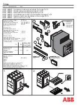
Installation and removal instructions
for IZM series fixed breaker
three-way Type 32 cable interlock kit
EATON
www.eaton.com
Step 5
Attach the mounting plate
(I)
with the interlock assembly
(E)
and
cable bracket
(G)
installed in
Step 4
to the right side of the breaker
as shown in
. Start by removing the M6 hex bolt, nut lock
washer, and grounding (earthing) wire installed in the lower front
corner of the mounting foot . This bolt assembly will be re-installed
through the adapter plate near the end of this step .
Slide an M6 square nut
(J)
into the slot in the upper rear part of the
case with the flat face toward the outside . The nut may have to be
tapped to fully seat it into the slot . Install an M6 x 20 mm hex bolt
(L)
, a lock washer
(C)
, and a fender washer
(K)
into the square nut
a few turns . Locate another captive square nut in a slot in the upper
part of the case, forward of the square nut just installed . Install
another M6 x 20 mm hex bolt
(L)
, lock washer
(C)
, and fender wash-
er
(K)
combination in this square nut . Slide the spacer washers fully
against the case and the lock washers full against the heads of the
bolts . This creates a space into which the open slots in the top of
the mounting plate will slide . Now insert the mounting bracket slots
onto the upper bolts and rotate the bracket down against the side of
the breaker . Make sure that the trip paddle slides in behind the wire-
form trip lever, and the follower arm slides in behind the drive pin as
shown in
.
Re-install the lower front bolt assembly (removed earlier), making
sure to re-connect the ground (earth) wire . Tighten the upper bolts
to stabilize the plate . Now insert an M6 x 12 hex bolt
(A)
and M6
lock washer
(C)
through the rear plate and mounting foot, retaining
it with a square nut
(J)
on the inside of the mounting foot . Torque to
7–9 N·m (65–85 in-lb) .
Check the interference of the lever assembly to the breaker to
ensure that the trip paddle is BEHIND the trip lever, and the follower
arm is BEHIND the drive arm . If not, remove the mounting plate and
reinstall properly following the directions above . Check the clear-
ances between the end of the drive arm and the end of the follower
arm (this should be about 1–4 mm) . The tip of the pin on
the drive arm should protrude slightly beyond the follower arm . If
this condition is not observed, it may be necessary to adjust the
position of the mounting plate relative to the breaker using upper
spacer washers .
(J)
(K)
(C)
(C)
(A)
(L)
Figure 8. Details for Step 5
Figure 9. Details for Step 5
Trip paddle
Trip lever
Follower arm
Drive arm