16
Installation
EATON ICUBE 2.0
UM.ICUBE2.0.SG.0822 August 2022 www.eaton.com
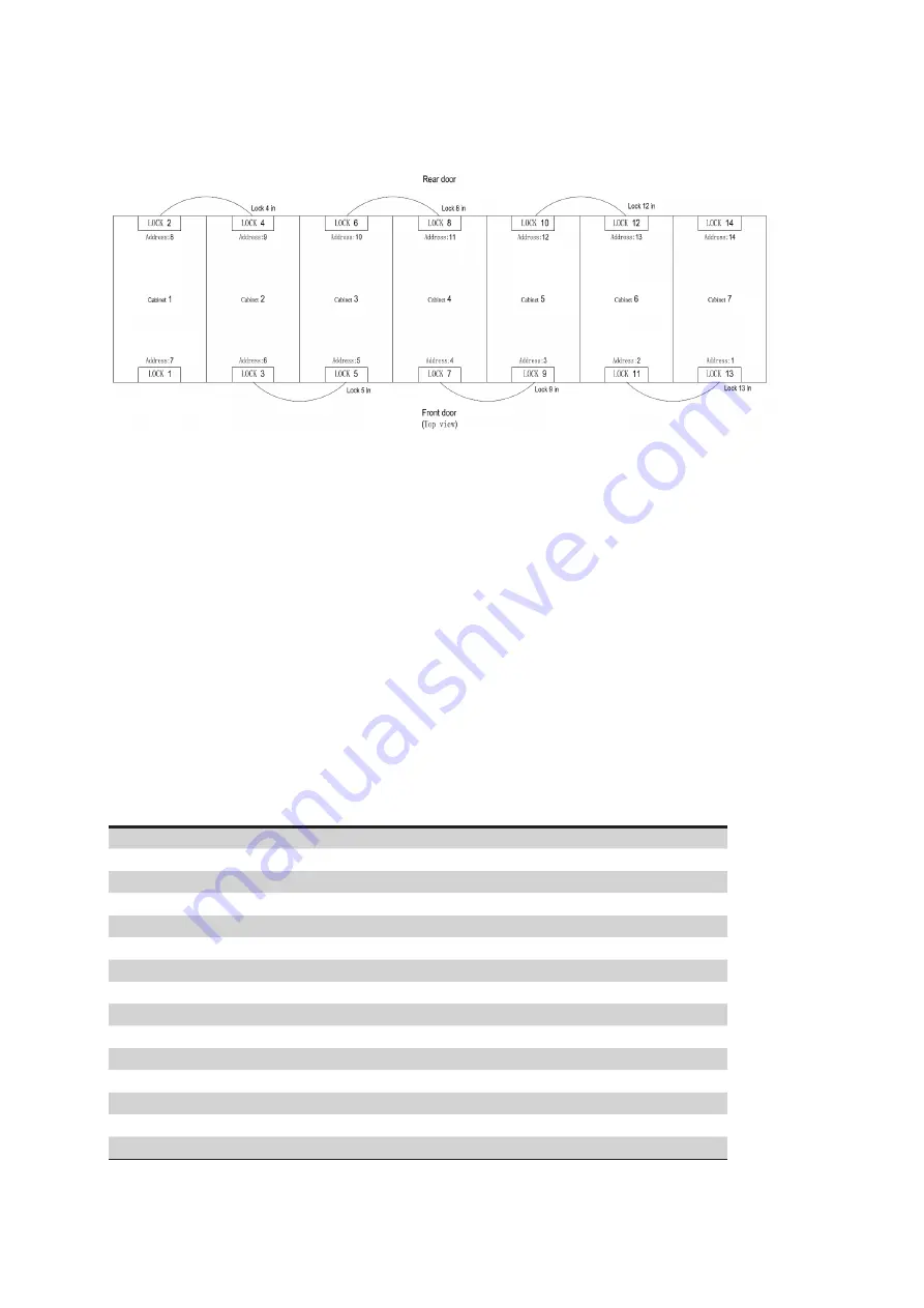
3.2.4 Communication to electronic locks
Figure 3 .11
1. Connect the network cable (Lock4 IN identifier) remainning on the top of cabinet1 to the in port of the elec-
tronic lock on the rear door of cabinet2
2. Connect the network cable (Lock5 in identifier) remainning on the top of cabinet 2 to the in port of the elec-
tronic lock on the front door of cabinet 3
3. Connect the network cable (Lock8 in identifier) remainning on the top of cabinet 3 to the in port of the elec-
tronic lock on the rear door of cabinet 4
4. Connect the network cable (Lock9 IN identifier) remainning on the top of cabinet 4 to the in port of the elec-
tronic lock on the front door of cabinet 5.
5. Connect the network cable (Lock12 in identifier) remainning on the top of cabinet 5 to the in port of the elec-
tronic lock on the rear door of cabinet 6
6. Connect the network cable (Lock13 IN identifier) remainning on the top of cabinet 6 to the in port of the elec-
tronic lock on the front door of cabinet 7
Electronic lock address setting method
Facing the front door of the cabinet, set address 1 to the right front door and address 2 to the left... The rear door
connects to the leftmost cabinet 11,12,13...... . See other cabinets as shown in the figure: 3.12 above (3 cabinets,
5 cabinets, also set the lock address in this way)
Address \ Location
No. 1
No. 2
No. 3
No. 4
No. 5
No. 6
Address no. 0
0
0
0
0
0
0
Address no. 1
1
0
0
0
0
0
Address no. 2
0
1
0
0
0
0
Address no. 3
1
1
0
0
0
0
Address no. 4
0
0
1
0
0
0
Address no. 5
1
0
1
0
0
0
Address no. 6
0
1
1
0
0
0
Address no. 7
1
1
1
0
0
0
Address no. 8
0
0
0
1
0
0
Address no. 9
1
0
0
1
0
0
Address no. 10
0
1
0
1
0
0
Address no. 11
1
1
0
1
0
0
Address no. 12
0
0
1
1
0
0
Address no. 13
1
0
1
1
0
0
Address no. 14
0
1
1
1
0
0


