background image

28

Eaton Ferrups FX UPS P-164000906 Eaton Ferrups FX User’s Guide P-164000906—Rev 05

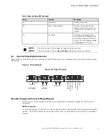
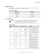
Table 11. Relay-MS Card

No

Function

Description

1

Not used

2*

Battery fault (Config 2)
UPS power off (Config 1)

Config 2:

a battery fault occurred

3

Not Used in Eaton FX

Not Used in Eaton FX

4

Load on utility**

The load is protected. The UPS supplies
the load using utility power (not from the
battery).

5

Common

Config 2:

volt-free pin.

Config 1 or 3:

pin connected to GND.

6

Load on automatic bypass***

The load is not protected. The UPS
supplies the load using utility power. If
utility power fails, the load will not be
supplied.

7

Low battery

The battery has dropped below the
preset warning level (depending on UPS
setup). If the voltage level continues to
drop, the UPS will no longer be capable
of supplying power to the load.

8

UPS ON, load powered

The UPS is operational and can supply
power to the load, whether utility power
is available or not, whether the UPS is on
the bypass or not.

9

Load on battery**

The load is protected. The UPS supplies
the load from the battery (not using
utility.

NOTE 1

*The function of this pin varies, depending on the configuration. the battery fault
information is available only in Config 2.

NOTE 2

**Load on utility and Load on battery are complementary signals. They cannot be
activated simultaneously.

NOTE 3

***Not available on line-interactive UPS. No manual bypass.

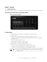
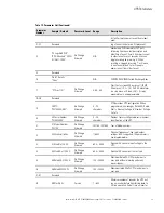
Table 12. Industrial Relay-MS

Relay

Function

Description

K1

UPS ON, load powered

The UPS is operational and can supply
power to the load, whether utility power
is avalible or not, whether the UPS is on
the bypass or not.

K2

Load on battery

The load is protected. The UPS supplies
the load from the battery (not using utility
power).

Communications

Summary of Contents for Ferrups FX

Page 1: ...p n P 164000906 Revision 05 Ferrups FX UPS Eaton Ferrups FX User s Guide Eaton Ferrups FX UPS...

Page 2: ...an radiate radio frequency energy and if not installed and used in accordance with the instruction manual may cause harmful interference to radio communications Operation of this equipment in a reside...

Page 3: ...his symbol indicates that you should not discard the product in the trash This product must be disposed of properly For more information contact your local recycling reuse or hazardous waste center Th...

Page 4: ...id or unenforceable the remaining provisions of this Agreement will remain in full force 5 5 Waiver The waiver by either party of any default or breach of this Agreement will not constitute a waiver o...

Page 5: ...wired Installation 11 4 2 Recommended Breaker And Wire Sizes 11 4 3 UPS Terminal Connections 12 4 4 BPE Bypass Switch Operation 13 4 5 BPE Bypass System Wiring Diagrams 15 5 5 B Ba at tt te er ry y C...

Page 6: ...ro ou ub blle es sh ho oo ot tiin ng g 5 59 9 10 1 Accessing the UPS Log 59 10 2 Displaying Active Alarm Conditions 60 10 3 Silencing the Alarm 61 10 4 Detecting an Alarm Condition 61 10 5 Troubleshoo...

Page 7: ...Figure 7 Break Before Make Bypass Switches 14 Figure 8 BPE External Bypass Switch Terminal Wiring Label 15 Figure 9 FX 3100 60 Hz 120 Vac Input 120 Vac Output Using a BPEFX Bypass Switch 17 Figure 10...

Page 8: ...viii Eaton Ferrups FX UPS P 164000906 Eaton Ferrups FX User s Guide P 164000906 Rev 05 List of Figures...

Page 9: ...ble 16 Enter a User Password 36 Table 17 Display a Parameter 36 Table 18 Changing a Parameter 37 Table 19 Parameter List 37 Table 20 Remote Control Display Configuration menu 44 Table 21 UPS Phase Che...

Page 10: ...x Eaton Ferrups FX UPS P 164000906 Eaton Ferrups FX User s Guide P 164000906 Rev 05 Table 40 Battery Specification 77 List of Tables...

Page 11: ...y ground from the UPS and the equipment connected to the UPS To reduce the risk of fire or electric shock install this UPS in a temperature and humidity controlled indoor environment free of conductiv...

Page 12: ...he e U UP PS S Perform an external inspection of the shipment When the UPS arrives inspect the shipment for any signs of damage Do not attempt to install the UPS system if damage is apparent If any d...

Page 13: ...4000906 Eaton Ferrups FX User s Guide P 164000906 Rev 05 3 6 Retract the leveling feet by turning them counter clockwise then carefully roll the cabinet down to its intended operating location Receivi...

Page 14: ...4 Eaton Ferrups FX UPS P 164000906 Eaton Ferrups FX User s Guide P 164000906 Rev 05 Receiving and Unpacking The UPS...

Page 15: ...D Figure 2 Eaton Ferrups FX Remote Control Display 2 2 2 2 B Ba at tt te er ry y C Ca ab biin ne et ts s If you need extended runtime contact Eaton or your local distributor for information on adding...

Page 16: ...nuous Ratings T V Continuous BPEFXMBB02 40A 300 Vac 50A 300 Vac BPEFXMBB04 80A 300 Vac 80A 300 Vac BPEFXMBB05 104A 300 Vac 120A 300 Vac Table 3 Available Break Before Make Bypass Switch Models Model N...

Page 17: ...It offers five isolated dry contact outputs and one isolated dry contact input See Table 12 for card functionality Industrial Gateway M2 The Eaton Industrial Gateway Card INDGW M2 combines the feature...

Page 18: ...8 Eaton Ferrups FX UPS P 164000906 Eaton Ferrups FX User s Guide P 164000906 Rev 05 Communication Overview...

Page 19: ...her from the unit than the standard cables allow contact your service representative or your local distributor for assistance Install the system on a level floor suitable for heavy weight and wheeling...

Page 20: ...ws to the floor the anchor brackets are attached to the base itself 1 Select the location for the brackets at the floor intersection beside the intended UPS cabinet location 2 Roll the UPS cabinet to...

Page 21: ...UPS is taken completely offline Be sure to read section 1 1 Safety Warnings before installing the UPS as stated Complete section 3 1 Location Requirements Continue to section 4 1 UPS Hardwired Install...

Page 22: ...is table because of temperatures number of conductors in the conduit or long service runs Follow local code requirements 4 4 3 3 U UP PS S T Te er rm miin na all C Co on nn ne ec ct tiio on ns s UPS A...

Page 23: ...nnecting the load from UPS output power A BBM switch breaks the original connection before it makes a new one If you turn a BBM switch from UPS to LINE the switch disconnects the load from UPS output...

Page 24: ...ve a Eaton bypass switch with a AC disconnect switch or the fuse box or panel is out of sight you must install a separate disconnect switch next to the UPS 4 Remove the screws in the lower part of the...

Page 25: ...IL AND ARE BONDED TO CHASSIS GROUND INSTALLATION TO BE PERFORMED BY A QUALIFIED ELECTRICIAN Table 7 Available Make Before Break Bypass Switch Models Model Number Ratings UL CSA Continuous Ratings T V...

Page 26: ...s NOTE 8 Use only Eaton supplied power cables between the UPS and battery cabinet NOTE 9 The customer must provide and install this ground connection according to NEC or local code requirements This g...

Page 27: ...nd External Batteries Load Distribution Panel Bulding Service Panel GR IG L1 N FX 3100 120V In 120V Out Using a BPE Bypass Switch 9 12 11 15 14 13 5 8 7 1 4 3 Bypass Switch BUILDING GROUNDING ELECTROD...

Page 28: ...18 Eaton Ferrups FX UPS P 164000906 Eaton Ferrups FX User s Guide P 164000906 Rev 05 BPE Bypass System Wiring Diagrams...

Page 29: ...ve rings and metal wristwatches or other metal objects and jewelry Don t carry metal objects in your pockets where the objects can fall into the external battery cabinet Tools must have insulated hand...

Page 30: ...ou may need to install larger battery cables in conduit between the external battery cabinets and the UPS to help with EMC performance The UPS must have a DC disconnect switch or a removable plug so y...

Page 31: ...battery cabinets if you have more than one We suggest routing battery cables through flexible conduit For models with a removable DC plug at the UPS end of the cables we suggest routing the cables thr...

Page 32: ...ation diagram Next use the voltmeter to check the DC voltage between the negative terminals of the strings The measured voltage should be less than 3V If it is more than 3V correct any wiring errors b...

Page 33: ...aton Ferrups FX User s Guide P 164000906 Rev 05 23 Model Nominal Battery Voltage FX3100 48Vdc After you have checked the DC voltage turn the DC switch on the external battery cabinet s to the OFF posi...

Page 34: ...of Cabinets Part Cable QTY Length GA Termina on Labeling 1 BAA 0212 15 1 108 1 15 16 1 108 1 16 1 BAA 0203 15 1 108 1 15 15 BAA 0204 16 1 108 1 16 16 Internal Wire Table Part Cable QTY Length GA Termi...

Page 35: ...21 21 Internal Wire Table Part Cable QTY Length GA Termina on Labeling BAA 0193 2 9 14 1 2 BAA 0207 5 2 24 1 5 BAA 0208 6 2 32 1 6 P 175000115 17 1 45 1 17 P 175000116 18 1 35 1 18 P 175000117 19 1 38...

Page 36: ...26 Eaton Ferrups FX UPS P 164000906 Eaton Ferrups FX User s Guide P 164000906 Rev 05 FXEBM03 FXEBM06 Wiring Diagram...

Page 37: ...o the Eaton FX USB communication port on the back of the UPS using an appropriate USB communication cable Connectivity cards allow the UPS to communicate in a variety of networking environments and wi...

Page 38: ...er be capable of supplying power to the load 8 UPS ON load powered The UPS is operational and can supply power to the load whether utility power is available or not whether the UPS is on the bypass or...

Page 39: ...ing contacts for Minislot 6 6 2 2 I In np pu ut t a an nd d O Ou ut tp pu ut t S Siig gn na all C Co on nn ne ec ct tiio on ns s Signal Inputs for external connections are located on the UPS back pane...

Page 40: ...sed REPO Configuration For Normally closed operation add a jumper between pins 3 and 4 of the REPO connection and the EPO switch should be connected to Pins 1 and 2 and should be closed during normal...

Page 41: ...oupler circuit that provides a 5VDC 1 mA signal that can be used to provide notification that the UPS is on battery For a general purpose relay contact the Relay Card MS can be ordered Alarm Contacts...

Page 42: ...32 Eaton Ferrups FX UPS P 164000906 Eaton Ferrups FX User s Guide P 164000906 Rev 05 Input and Output Signal Connections...

Page 43: ...the correct operating mode and updates automatically AVR Displays Off Normal Buck or Boost if the UPS is operating normally but utility is outside normal operating thresholds ABM Status of the ABM Cha...

Page 44: ...kup power when needed Off The UPS cannot provide battery backup power because The UPS is in the Off mode The UPS may be running on battery power Inverter Mode Flashing The UPS is in Line Condition Mod...

Page 45: ...ns AC input power and provides the conditioned power to your equipment The AC LINE and READY indicators should be illuminated in this mode Line Condition Press CONTROL 3 ENTER ENTER The UPS is conditi...

Page 46: ...assword Press This Key Display Shows CLEAR EATON FX PROGRAM Password 0 0 0 3 7 7 Password 000377 ENTER Level User To clear the password press CLEAR until Password Cleared appears on the remote control...

Page 47: ...Bot Xfmr Charger AcScr Dvr1 Dvr2 Display cycles through all temperatures Scrolls to next temperature every 3 seconds User can toggle scrolling by pressing 0 When scrolling is stopped pressing 1 will m...

Page 48: ...alarm if this value is too high This parameter is only for models that monitor transformer temperature for other models this parameter will always show 63 C 15 15 Unit ID Network 1 UPS No Change Allow...

Page 49: ...39 39 CTO FX310000AAA1 No Change Allowed 0 20 characters CTO describes UPS configuration When programmed also changes Rated VA Rated Watts Nominal Voltage In Nominal Voltage Out etc 40 40 Serial Numbe...

Page 50: ...er action taken 64 Reserved 65 65 Shtdwn 1 750 VPC User 1 670 2 100 When using custom batteries the battery voltage shutdown level load off and UPS shuts off Alarm setpoint for low battery condition 6...

Page 51: ...rogramming to 0 will disable Probe Missing alarm 81 81 AutoMaxPLLError 10 0 User 0 0 6553 5 Maximum Angle Error allowed by the PLL to remain locked in Auto Mode 82 82 LCMaxPLL Error 30 0 User 0 0 6553...

Page 52: ...M data 98 98 EBM4 0 NONE User 0 NONE 1 FXEBM01 3 FXEBM03 4 FXEBM04 5 FXEBM05 6 FXEBM06 7 FXEBM07 8 FXEBM08 Updates ABM with attached EBM data 99 105 Reserved 106 106 EPO 0 Disabled User 0 Disabled 1 E...

Page 53: ...ation port for Minislot 2 1 Activate 118 118 SiteWiringDetect 1 Enabled User 0 Disabled Allows enabling and disabling of checking for site wiring fault 1 Enabled 119 119 AutoRestart 1 Enabled User 0 D...

Page 54: ...ote Control Display includes a Configuration Menu that lets you adjust the brightness of the LED LCD backlight and the Lightbar Table 20 Remote Control Display Configuration menu Remote Control Displa...

Page 55: ...e keypad press the CLEAR and ENTER buttons at the same time 3 Enter in code 0 8 2 0 4 9 then press the ENTER button Keypad will then read unlocked Locking the Keypad Press This Key Display will Show C...

Page 56: ...46 Eaton Ferrups FX UPS P 164000906 Eaton Ferrups FX User s Guide P 164000906 Rev 05 Locking and Unlocking the Remote Control Panel...

Page 57: ...all hardwired connections are complete including external battery cabinets if applicable complete the phase check using the following steps You will need an AC voltmeter for the phase check Before ope...

Page 58: ...efore Break type verify that the AC voltages from the UPS and the AC line are in phase Measure the voltage between the following points on the terminal strip These measurements must be no more than 10...

Page 59: ...he UPS and turn the bypass switch to the UPS position 8 8 3 3 I In niit tiia all S St ta ar rt tu up p P Pa ar ra am me et te er rs s Before programming the initial startup parameters enter the user l...

Page 60: ...e Eaton FX Ferrups UPS can be programmed for up to four FX battery runtime options To set the battery cabinet options you can program each cabinet type into parameters 95 98 1 Choose the type of batte...

Page 61: ...Setup for Using a Custom Non Eaton Ferrups FX Battery Configuration To set the UPS for a customer supplied battery configuration the following parameters must be set with the user level password Tabl...

Page 62: ...ttery discharge test feature When ABM is enabled by default the battery discharge test will run automatically every 90 days The duration of the battery test can be modified by changing parameter 93 93...

Page 63: ...e equipment into standard wall outlets and restart the equipment UPSs with a BPE type Break Before Make BBM bypass switch see the label inside the switch shut down the protected equipment Turn the byp...

Page 64: ...inets do require some attention to assure continued reliable service Eaton recommends that you schedule preventive maintenance checks at least every six months At these checks the service technician s...

Page 65: ...rews 3 Grasp the receptacle panel from both sides and pull the assembly straight out from the back of the unit Installation of a Replacement Receptacle Panel 1 Insert the new receptacle panel assembly...

Page 66: ...nd tighten the screws that secure the receptacle panel in place Screws Screws 3 Turn the receptacle panel main breaker to the ON position If the UPS was placed in standby mode prior to replacing the r...

Page 67: ...battery or batteries Released electrolyte is harmful to the skin and eyes It may also be toxic CAUTION Do not discard the UPS or the UPS batteries in the trash This product contains sealed lead acid...

Page 68: ...g t th he e U UP PS S F Fiir rm mw wa ar re e To keep the UPS firmware updated with the latest improvements and benefits visit www eaton com ferrupsfx often for updates You can download the latest fi...

Page 69: ...events and status information in the UPS log To view the UPS log from the remote control display do the following Press this key Display shows DISPLAY Display 2 4 Display 24 ENTER 24 Log The display a...

Page 70: ...arm status or event The date and time stamp of the entry 1 10 0 2 2 D Diis sp plla ay yiin ng g A Ac ct tiiv ve e A Alla ar rm m C Co on nd diit tiio on ns s Access parameter 20 to view any active ala...

Page 71: ...he number 5 Press the ENTER button Press the ENTER button To silence the alarm temporarily until a new alarm becomes active press the following buttons on the Remote Control Display Press CONTROL Pres...

Page 72: ...ned on Make sure the front panel RCD is properly plugged in the front of the UPS If UPS is still turned off and appears dead call Eaton Service UPS will not start although front panel seems to be on F...

Page 73: ...k and forth between AC and Battery Input AC is not stable On If a generator is being used as AC input check if ON Gen signal has been activated at the rear ports of the UPS USB Port at the rear panel...

Page 74: ...ehavior If UPS is in Keep Alive Mode Check Input Circuit Breaker CB if it is Off If it is Off check AC Input Source and make sure it is compatible with the UPS ratings If input AC Source measures good...

Page 75: ...tart until the eeprom is reset Call Eaton Service 8 SHUTDOWN IMMINENT A UPS Supporting Load with Battery but Battery Voltage has reached a very low level and the UPS is about to drop load and switch t...

Page 76: ...5 hysteresis for alarm to clear 21 LEVEL 3 OVERLOAD A Load 115 Will shut off in a short time minimum 10 seconds Reduce Load to 100 5 hysteresis for alarm to clear 22 SYSTEM INITIALIZATION ERROR A Cont...

Page 77: ...TERY Status UPS in Battery Mode Supporting Load on Battery Nothing 41 UPS ON NORMAL Status UPS in Line Mode Supporting Load Nothing 42 BATTERY TEST IN PROGRESS Status UPS in Line Mode Supporting Load...

Page 78: ...e load cannot be shutdown you would be using an external Bypass Switch that Eaton can provide Turn the switch to Service Mode and call Eaton Service 68 UPS SHUTDOWN Status UPS off Off Nothing 69 RCD C...

Page 79: ...is not disabled or ABM is not disabled 86 ABM FAILED FLOAT MODE N Battery voltage did not reach 2 3 VPC in allotted time Normally 24 hours Supporting Load Battery Charger disabled Replace batteries 8...

Page 80: ...TRIP A Charger reporting over temperature and turned off On but charger is off Call Eaton Service 95 SCR OVERTEMPERA TURE A SCR Heatsink on AC Board reporting over temperature On Call Eaton Service 96...

Page 81: ...ort representative United States 1 800 356 5737 Option 2 Option 1 for technical support Canada 1 800 461 9166 option 4 Option 1 Option 1 for on site service dispatching or 1 800 356 5737 Option 2 Opti...

Page 82: ...72 Eaton Ferrups FX UPS P 164000906 Eaton Ferrups FX User s Guide P 164000906 Rev 05 Service and Support...

Page 83: ...150 Joules per UPS chassis Inrush Current Inrush current at power up 250 amps for one cycle ABF Protection Anti Backfeed protection compliant with UL1778 5th ED Regulation 3 load regulation under any...

Page 84: ...Mode operation in zero milliseconds Efficiency The UPS efficiency with Line to Line Load shall be 80 with charger off The UPS efficiency with Line to Neutral Load shall be 88 with charger off 1 12 2 2...

Page 85: ...0 14 25 20 748 79 29 48 592 73 23 34 517 35 20 37 715 16 28 16 1 12 2 4 4 B By yp pa as ss s S Sw wiit tc ch he es s Table 34 Available Make Before Break Bypass Switch Models Model Number Ratings UL C...

Page 86: ...38 Battery Cabinet Weight Eaton FERRUPS FX Battery Option Cabinet Type Battery Type Weight Type N Battery Cabinet With No Batteries 142 lbs Type P Battery Cabinet With No Batteries 175 lbs FXEBM01 N...

Page 87: ...Ah 3 Strings 48V FXEBM06 w o UPS Internal Batteries Future Option 140Ah 3 Strings 48V FXEBM06 With Internal Batteries Future Option 140Ah 3 Strings 48V Charging profile is maintained by Eaton ABM char...

Page 88: ...78 Eaton Ferrups FX UPS P 164000906 Eaton Ferrups FX User s Guide P 164000906 Rev 05 Battery...

Page 89: ...1 1 T Tw wo o Y Ye ea ar r L Liim miit te ed d W Wa ar rr ra an nt ty y U US S a an nd d C Ca an na ad da a For warranty information please refer to the Resources link on our website Two Year Limited...

Page 90: ...P 16400090605 P 164000906 05...

Reviews: