


14
Eaton Ferrups FX UPS P-164000906 Eaton Ferrups FX User’s Guide P-164000906—Rev 05
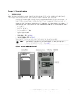
Figure 6. Make Before Break Bypass Switches
BPEFXMBB02
BPEFXMBB04
BPEFXMBB05
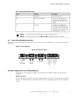
Figure 7. Break Before Make Bypass Switches
BPEFXBBM02
BPEFXBBM04
BPEFXBBM05
BPE Bypass Switch Installation
1.
Select the proper diagram that applies to your Eaton Ferrups FX series UPS.
2.
Review the installation diagram and applicable notes to find the proper circuit breaker size for your
installation. in the U.S. see the following table to size the wire.
3.
Mount the bypass switch within sight of the UPS. If you do not have a Eaton bypass switch with a AC
disconnect switch or the fuse box or panel is out of sight, you must install a separate disconnect switch
next to the UPS.
4.
Remove the screws in the lower part of the bypass switch front cover and remove the lower cover panel.
5.
Remove the knockouts or plugs in the bottom of the bypass switch for AC Line Input, AC to UPS Input, AC
from UPS Output, and AC to the UPS load.
6.
Remove the wiring cover from the back of the UPS.
7.
Remove the knockouts in the UPS wiring cover for AC Input and AC Output.
8.
Install the conduit adapter. AC Input and AC Output conductors must be run through separate pieces of
conduit. UPS Output circuits shall be installed in dedicated conduit systems and not shared with other
electrical circuits.