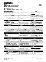
HPT_ZC1
IRIG-B-
RO1 NO
IRIG-B+
RO2 NO
RO3 CMN
RO3 NO
RO4 CMN
RO4 NO
RO3 NC
RO4 NC
1
3
2
4
5
6
7
8
9
10
11
12
13
14
15
16
17
18
PE
N.C.
N.C.
N.C.
+
−
Analog Output
Fig. 14: RO-3AI - Pin Assignment
For details on the Analog Output please refer to the Technical Data,
Relay Outputs
The Relay Outputs are potential-free contacts.
The assignment of the Relay Outputs is described in
╚═▷ “Relay Output Configuration”
Check the “EMR-3MP0 Reference Manual” (separate document) for a list of signals that
can be assigned.
CAUTION!
Please carefully consider the current carrying capacity of the Relay Outputs. Please refer
to the Technical Data (
Selfsupervision Contact
The Selfsupervision Contact contact (“SC”) cannot be configured. It is a changeover (Form
“C”) contact that picks up when the device is free from internal faults. While the device is
booting up, the “SC” relay remains dropped-off (unenergized). As soon as the system is
properly started (and protection is active), it picks up and the assigned LED is activated
accordingly (please refer to the Self Supervision chapter,
).
78
www.eaton.com
EMR-3MP0
2 Hardware
2.2 EMR-3MP0 – Installation and Wiring