Pilz 773 815, Operating Manual
The Pilz 773 815 is a cutting-edge device, designed to elevate your operational experience. This Operating Manual is an essential companion, providing detailed instructions for seamless usage. Available for free download at manualshive.com, it ensures you have the necessary resources to maximize the potential of your Pilz 773 815.
Share
Download


Reviews:
No comments
Related manuals for 773 815

MCS Series
Brand: Eaton Pages: 6

MRI3
Brand: Woodward Pages: 68

Protectorelay
Brand: resideo Pages: 8

CK3-105J
Brand: Riyue Pages: 2

YTC YT-520 Series
Brand: MIEPL Pages: 9

V364
Brand: Iseo Pages: 4

NDR1E-38 Series
Brand: nader Pages: 16

LUT-SHUNT-FM
Brand: LVS Pages: 4

PKZM4-40
Brand: Eaton Pages: 2
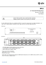
RP12
Brand: Qtx Pages: 4

5XA 998 572-001
Brand: Hella marine Pages: 2

SRB 301MC
Brand: schmersal Pages: 8

GSM-R5-T
Brand: SEA Pages: 6

REE-5001
Brand: KMC Controls Pages: 2

FlexStat BAC-12xx36 Series
Brand: KMC Controls Pages: 11

IM30-DK
Brand: MICROENER Pages: 34

774135
Brand: Pilz Pages: 12


