SLX9000 Adjustable Frequency Drives User Manual
MN04003020E
For more information visit:
www.eaton.com
4-1
January 2009
Chapter 4 — Control Wiring
Control Unit
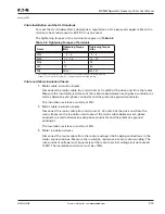
MF4 – MF6 460V
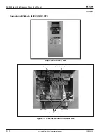
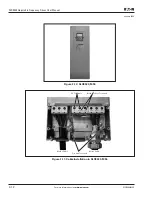
In frames MF4 – MF6 there are two option board connectors SLOT D and SLOT E (see
Figure
4-1
). Newest software supports hardware with two board slots. Also older software versions
can be used, but they will not support hardware with two board slots.
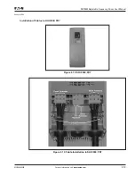
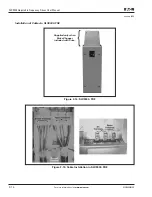
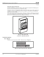
Figure 4-1: Option Board Slots D and E in Frames MF4 – MF6
460V only.
Allowed Option Boards in MF4 – MF6
See below for the allowed option boards in the two slots on MF4 – MF6 drives.
When two option boards are used, the one in slot E has to be OPTAI or OPTAA. Do not use
two OPTB_ or OPTC_ boards. Also, combinations of OPTB_ and OPTC_ boards are prohibited.
See descriptions for OPTAA and OPTAI option boards in
Appendixes B
and
C
.
All 230V, FR7 – FR8 460V and All 575V
The control unit of FR7 and FR8 drives consists of the control board and various option
boards that plug into the five slot connectors (A to E) of the control board.
Galvanic isolation of the control terminals is provided as follows:
●
The control connections are isolated from power, and the GND terminals are
permanently connected to ground.
●
The digital inputs are galvanically isolated from the I/O ground.
●
The relay outputs are double-isolated from each other at 300V AC.
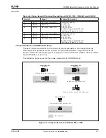
SLOT D
C3
C4
C6
C7
CI
CJ
SLOT E
AA
AI
B1
B2
B4
B5
B9
C2
C3
C4
C6
C7
C8
CI
CJ
S
lot E: I/O Boards, Fieldbus Boards
a
n
d Expa
n
ders
S
lot D: Fieldbus Boards
D
E
Summary of Contents for Cutler-Hammer SLX9000 Series
Page 1: ...SLX9000 Adjustable Frequency Drives User Manual Effective January 2009 Supersedes October 2008...
Page 2: ......
Page 171: ......


