Eaton Cutler-Hammer Digitrip RMS 810, Instructions Manual
The Eaton Cutler-Hammer Digitrip RMS 810 is a top-tier circuit breaker with advanced trip unit technology. To ensure seamless operation, we provide a comprehensive Instructions Manual for free download on our website. Get your manual today at manualshive.com and optimize the performance of your RMS 810 effortlessly.
Share
Download


Reviews:
No comments
Related manuals for Cutler-Hammer Digitrip RMS 810

VM1-T
Brand: ABB Pages: 44

ZX0
Brand: ABB Pages: 78

DFS 6 A EV OCP Series
Brand: Doepke Pages: 2

SV 9677.000
Brand: Rittal Pages: 16

Metasol 1600A
Brand: LS ELECTRIC Pages: 19

Power Defense IZMX40
Brand: Eaton Pages: 30

BA88-35
Brand: IEK Pages: 19

50DHP-VR
Brand: Eaton Pages: 44

DS-206S series
Brand: Eaton Pages: 96

Westinghouse DB-100
Brand: NATIONAL SWITCHGEAR Pages: 42

Emax E1.2
Brand: ABB Pages: 109
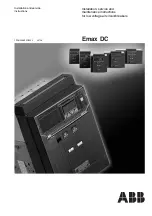
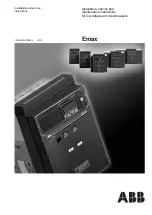
Emax DC L3447
Brand: ABB Pages: 112
E1B 08
Brand: ABB Pages: 161

ADVAC 38
Brand: ABB Pages: 56

3VT9100-4TN30
Brand: Siemens Pages: 4

3VT9100-8CE00
Brand: Siemens Pages: 4

PVDB-28kV
Brand: GE Pages: 31

AIRPAX SNAPAK
Brand: Sensata Pages: 13


