Effective November 2010Supersedes IB 33-790-1I Dated 10/98
Instruction Booklet
IB 33-790-1J
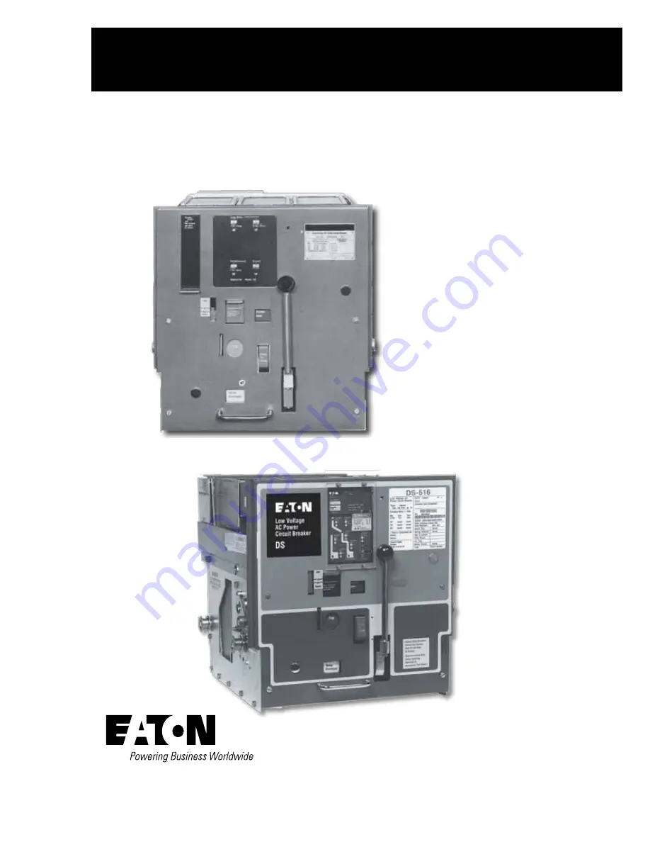
Instructions for Low Voltage PowerCircuit Breakers Types DS and DSL
Page 1: ...Effective November 2010 Supersedes IB 33 790 1I Dated 10 98 Instruction Booklet IB 33 790 1J Instructions for Low Voltage Power Circuit Breakers Types DS and DSL...
Page 2: ...Instruction Booklet IB 33 790 1J Effective November 2010 Instructions for Low Voltage Power Circuit BreakersTypes DS and DSL eaton corporation www eaton com This Page Left Intentionally Blank...
Page 3: ...ent Manual and Power operated Breakers 12 3 1 1 Closing Facilities 12 3 1 2 Tripping Facilities 12 3 2 Levering Device 12 Section 4 Basic Operating Instructions 13 4 0 General 13 4 1 Levering Device 1...
Page 4: ...1 Moving Contact Sub assemblies 6 2 Stationary Contact Sub assemblies Section 7 Arc Chute 53 7 0 General 53 Section 8 Circuit Breaker Automatic Tr ipping System 55 8 0 General 55 8 1 The Amptector II...
Page 5: ...1 3 2 DS 416 DS 416S DS 420 DS 632 and DS 840 78 12 1 4 Arc Chutes 78 12 1 5 General Inspection 78 12 1 5 1 Power Operated Mechanisms 78 12 2 Factory Adjustments 79 12 2 1 Trip Latch Overlap 80 12 2...
Page 6: ...echanism 21 18 Emergency Spring charge on Power operated Mechanism 21 19 Standard Schematic and Connection Diagrams for Power Operated Breakers 22 20 Principal Parts in a Manually Charged Spring Opera...
Page 7: ...Details 53 57 DS 632 Arc Chute with Details 53 58 DS 840 Arc Chute with Details 54 59 Schematic Illustration of Tr ipping System 55 60 Standard Amptector II A Solid State Tr ip Unit 56 61 Amptector II...
Page 8: ...eaton corporation www eaton com Figure Title Page 86 Contacts and Their Adjustment DS 632 Breaker 76 87 Contacts and Their Adjustment DS 840 Breaker 77 88 Open Position Stop and Anti rebound Latch 78...
Page 9: ...st be strictly adhered to All possible contingencies which may arise during installation operation or maintenance and all details and variations of this equipment do not purport to be covered by these...
Page 10: ...Circuit BreakersTypes DS and DSL eaton corporation www eaton com CAUTION The circuit breakers described in this book were designed and tested to operate within their nameplate ratings Operation outsid...
Page 11: ...EE standards TYPE DS AND DSL BREAKERS ARE PROTECTIVE DEVICES AS SUCH THEY ARE MAXIMUM CUR RENT RATED DEVICES THEREFORE THEY SHOULD NOT UNDER ANY CIRCUMSTANCES BE APPLIED OUTSIDE THEIR NAMEPLATE RATING...
Page 12: ...interlocks and three insulated pole unit assemblies mounted on a base On the front of the breaker are the control items needed for proper operation of the circuit breaker They are breaker position in...
Page 13: ...the one piece molded base of the DS 206 2 DS 206S uses the DS 416 arc chute 3 DS 206S main disconnects have 50 more fingers than the DS 206 4 DS 206S has twice as many main contacts and arms as the D...
Page 14: ...s while it is being levered into or out of its cell or while it is standing in any intermediate location between the TEST and the CONNECT positions or the DISCONNECT position 5 Provisions for Padlocki...
Page 15: ...bolted tightly before inserting breaker into cell 6 Do not lift breaker with ordinary crane hooks ropes chains etc to avoid possible damage to parts or dropping the unit Use breaker lifting adapter 7...
Page 16: ...lace the arc chutes and insulating barriers and proceed as described in Section 3 1 1 STORING If it is necessary to store the equipment before installa tion keep it in a clean dry place protected from...
Page 17: ...aw as Shown 2 2 REMOVING SHIPPING BRACE Before the circuit breaker element can be withdrawn from its compartment for the first time two shipping braces must be removed from the lower part of the break...
Page 18: ...rs Fig 4 Use of Breaker Lifting Adapter 6 With the breaker pulled completely to the end of the rails remove the two 2 six inch long pieces of split plastic tubing that are on the rear of the stationar...
Page 19: ...ys results from opening the breaker under load or short circuit conditions The Amptector solid state overcurrent tripping sys tem The remainder of the drawout element includes the fol lowing auxiliary...
Page 20: ...Circuit BreakersTypes DS and DSL eaton corporation www eaton com Fig 5b View Showing Controls on the Panel Post 1988 DIGITRIP RMS TRIP UNIT NAMEPLATE EMERGENCY CHARGING HANDLE OPEN CLOSE INDICATOR CLO...
Page 21: ...BreakersTypes DS and DSL eaton corporation www eaton com Fig 6a Left Side of Breaker with Levering Device Arm in REMOVE Position Fig 6b DS 416 Breaker with Front Panel Removed Fig 7 Right Side Showin...
Page 22: ...nd push on the close bar As optional equipment the electrical spring release attachment normally supplied only on power operated breakers can be supplied on manually operated breakers On power operate...
Page 23: ...The position indicator will be opposite DISC which is the DISCONNECT position wherein the breaker is held in its compartment with both main and secondary contacts disengaged If the crank is withdrawn...
Page 24: ...g automatically as the TEST position is reached 4 3 CLOSE THE BREAKER The breaker can be closed only when the following condi tions are met 1 The closing springs are charged 2 The levering arms are in...
Page 25: ...ing device worm shaft and turn the crank clockwise until the CONNECT position stop is reached as indicated by sudden increase in load on the crank as previously described in paragraph 4 1 Note however...
Page 26: ...ism is of the spring charged stored energy type This means that it consists of two major parts 1 The stored energy or spring charging mechanism 2 The mechanism for closing and opening the breaker The...
Page 27: ...illator 30 and emergency charge device 26 do not have internal flats but are mounted on separate bushings and are free to rotate on the crank shaft Figure 17 is an exploded view of the crankshaft part...
Page 28: ...tes move away from the ratchet wheel pin The ratchet wheel does not rotate during the closing operation thus preventing excessive wear on the teeth and pawls Power operated breakers are also equipped...
Page 29: ...90 1J Effective November 2010 Instructions for Low Voltage Power Circuit BreakersTypes DS and DSL eaton corporation www eaton com Fig 15 Front View Showing Major Parts of the Crank Shaft Assembly Some...
Page 30: ...Instruction Booklet IB 33 790 1J Effective November 2010 Instructions for Low Voltage Power Circuit BreakersTypes DS and DSL eaton corporation www eaton com Fig 16 Power Operated Spring Charge Detail...
Page 31: ...ffective November 2010 Instructions for Low Voltage Power Circuit BreakersTypes DS and DSL eaton corporation www eaton com Fig 17 Crank Shaft Assembly of Power Operated Mechanism Fig 18 Emergency Spri...
Page 32: ...ve November 2010 Instructions for Low Voltage Power Circuit BreakersTypes DS and DSL eaton corporation www eaton com Fig 19 Standard Schematic and Connection Diagrams for Power operated Breakers and T...
Page 33: ...eleased to close the breaker When the breaker closes the b contact opens to cut off spring release coil and motor and limit switch LS contacts reset If the close contact CS C is maintained the Y relay...
Page 34: ...f this spring charging device which is located between the mechanism right hand side frame and the right crank arm A part of this assembly is the manual charge cam which is rigidly fixed to the crank...
Page 35: ...ective November 2010 Instructions for Low Voltage Power Circuit BreakersTypes DS and DSL eaton corporation www eaton com Fig 22 These Sketches Show the Four Basic Positions of Breaker and Linkage with...
Page 36: ...onds to the angular position of the drive plates and closing spring crank arms shown in Figure 16b The trip latch is in the tripped position and it will reset to the latched position at the end of the...
Page 37: ...roller constraining link The down ward force on the main drive link results in a pulling force on the roller constraining link This force tends to rotate the trip latch counterclockwise but the trip l...
Page 38: ...67 68 and its operation is cov ered in Section 8 7 1 6 Blown Limiter Indicator See Fig 80 5 1 6 1 Miscellaneous Details Figure 26 shows a bottom view of the breaker drawout unit Visible in this pictur...
Page 39: ...wer Circuit BreakersTypes DS and DSL eaton corporation www eaton com Fig 26a Bottom View of Breaker Unit Showing Interfer ence Interlock Motor Cut off Switch and Other Details not Visible from Above F...
Page 40: ...To increase safety to personnel and the circuits to which the breaker is connected the complete unit is equipped with automatic mechanical interlocking This interlocking is effective in various ways...
Page 41: ...ion In this position the breaker has moved only a fraction of an inch into its compartment and will be shown by the position indicator In this position the following conditions exist A The breaker wil...
Page 42: ...lower projection see Figure 28a strikes the hook on the trip plate and the worm shaft will not be cleared So it is necessary to push the trip plate in which moves the hook back out of the way of the s...
Page 43: ...ipped when the crank handle is removed The breaker is held trip free so it cannot be closed Also by another interlock described later the close release latch cannot be released 5 1 8 1 Spring Discharg...
Page 44: ...to the REMOVE position as shown in a and b the lever ing shaft has turned counterclockwise until the lever ing device arms are horizontal to the rear As it rotates the close bar cam has been rotated c...
Page 45: ...sible a choice between being able to close the breaker by hand push on the Close bar and not being able to with the breaker in the CONNECT position Some consider it undesirable to do so Referring to F...
Page 46: ...through a control switch or other circuit mak ing device 5 1 8 3 Breaker Equipped for Electric Lockout Power operated breakers may be equipped for electric lockout meaning that closing an unenergized...
Page 47: ...padlocked in the trip free condition in which the breaker cannot be closed and the breaker can not be moved with the levering device This figure shows the relation of parts for padlocking in the trip...
Page 48: ...alignment by a welded steel frame Front and rear views of each are shown in Figures 39 and 40 for the DS416 Figures 41 and 42 for the DS420 Figures 43 and 44 for the DS632 Figures 45 and 46 for the D...
Page 49: ...blades are connected On the DS632 and DS840 there are two sets of contacting surfaces one vertically above the other for making contact with two corresponding rows of stationary contact fingers The a...
Page 50: ...ese springs are visible in the photograph of the DS206 only With this construction the pressure on the main contact surfaces is increased during the carrying and opening of high short circuit currents...
Page 51: ...on of the magnetic fields of the currents in each arcing contact finger causes the fingers to be attracted toward each other when closing against fault currents This results in a blow on action on the...
Page 52: ...nstruction Booklet IB 33 790 1J Effective November 2010 Instructions for Low Voltage Power Circuit BreakersTypes DS and DSL eaton corporation www eaton com Fig 37 Type DS 206 Pole Unit Assembly Front...
Page 53: ...nstruction Booklet IB 33 790 1J Effective November 2010 Instructions for Low Voltage Power Circuit BreakersTypes DS and DSL eaton corporation www eaton com Fig 38 Type DS 206 Pole Unit Assembly Rear V...
Page 54: ...Low Voltage Power Circuit BreakersTypes DS and DSL eaton corporation www eaton com Fig 39 Type DS 416 Pole Unit Assembly Front View Fig 40 Type DS 416 Pole Unit Assembly Rear View Fig 41 Type DS 420 P...
Page 55: ...Low Voltage Power Circuit BreakersTypes DS and DSL eaton corporation www eaton com Fig 43 Type DS 632 Pole Unit Assembly Front View Fig 44 Type DS 632 Pole Unit Assembly Rear View Fig 45 Type DS 840 P...
Page 56: ...truction Booklet IB 33 790 1J Effective November 2010 Instructions for Low Voltage Power Circuit BreakersTypes DS and DSL eaton corporation www eaton com Fig 47 Moving and Stationary Contact Details D...
Page 57: ...truction Booklet IB 33 790 1J Effective November 2010 Instructions for Low Voltage Power Circuit BreakersTypes DS and DSL eaton corporation www eaton com Fig 48 Moving and Stationary Contact Details D...
Page 58: ...truction Booklet IB 33 790 1J Effective November 2010 Instructions for Low Voltage Power Circuit BreakersTypes DS and DSL eaton corporation www eaton com Fig 49 Moving and Stationary Contact Details D...
Page 59: ...49 Instruction Booklet IB 33 790 1J Effective November 2010 Instructions for Low Voltage Power Circuit BreakersTypes DS and DSL eaton corporation www eaton com Fig 50 Moving Contact Details DS 632...
Page 60: ...50 Instruction Booklet IB 33 790 1J Effective November 2010 Instructions for Low Voltage Power Circuit BreakersTypes DS and DSL eaton corporation www eaton com Fig 51 Stationary Contact Details DS 632...
Page 61: ...51 Instruction Booklet IB 33 790 1J Effective November 2010 Instructions for Low Voltage Power Circuit BreakersTypes DS and DSL eaton corporation www eaton com Fig 52 Moving Contact Details DS 840...
Page 62: ...52 Instruction Booklet IB 33 790 1J Effective November 2010 Instructions for Low Voltage Power Circuit BreakersTypes DS and DSL eaton corporation www eaton com Fig 53 Stationary Contact Details DS 840...
Page 63: ...6 DS420 and DS632 assemblies with a smaller one on the DS206 and a slightly larger one on the DS840 Fig 54 Breaker with Barrier Removed to Show Mounting of Arc Chutes Fig 55 DS 206 Arc Chute with Deta...
Page 64: ...hute is shown in Figure 58 In addition to the steel plates the larger arc chutes include hard arc resisting glass polyester plates These plates produce turbulence in the exhaust gases above the steel...
Page 65: ...provides a very flexible system covering a wide range of tripping characteristics Not only is the Amptector trip unit adjustable but the sensors are avail able over a wide range of current ratings Th...
Page 66: ...ability of solid state devices The Amptector I A is an optional extra cost tripping system which can be provided when ground fault protection or trip indica tors are required Both trip units have the...
Page 67: ...R TRIPLE Each Amptector II A trip unit has a terminal block acces sible on the front of the circuit breaker front panel Figure 59 shows a typical standard wiring diagram which includes the Amptector I...
Page 68: ...ick up set ting 3 Short delay pick up 4 to 10 X sensor rating 4 Short delay 18 seconds to 50 seconds or 11 to 30 cycles at 60 Hz at 2 5 X pick up setting Over these ranges tripping will always occur w...
Page 69: ...59 Instruction Booklet IB 33 790 1J Effective November 2010 Instructions for Low Voltage Power Circuit BreakersTypes DS and DSL eaton corporation www eaton com...
Page 70: ...60 Instruction Booklet IB 33 790 1J Effective November 2010 Instructions for Low Voltage Power Circuit BreakersTypes DS and DSL eaton corporation www eaton com...
Page 71: ...nit ground element may be ener gized from an external ground current source rather than from internally developed ground current Such an exter nal source could be a ring type transformer through which...
Page 72: ...o check any pickup calibra tion Time delay calibrations can also be checked Place drawout breakers in DISCONNECT position before per forming Amptector trip unit check Special handling and test equipme...
Page 73: ...rip unit controls to the new desired values Available sensor ratings are listed in Table 4 Maximum continuous current rating for breaker Amptector trip unit Long Delay Pick up is adjustable from 50 to...
Page 74: ...is lever to strike a pin in the breaker mechanism trip shaft and rotate the latter in a clockwise direction to trip the breaker Fig 68 Undervoltage Trip Device Operation As the breaker opens a pin on...
Page 75: ...7 3 High Load Switch available with Amptector l A only This is a self resetting solid state device which picks up on an overload condition at a lower pick up value than the breaker overload trip setti...
Page 76: ...haft is in the reset position a normally closed con tact of the switch is closed see Figures 72 and 73 When this switch is supplied the contact is usually connected in the closing circuit of the circu...
Page 77: ...he test terminals of the Amptector trip unit A second cable connects to the source of input power Figures 75 and 76 show the tester and operating controls The ammeter is dual range and controlled by t...
Page 78: ...68 Instruction Booklet IB 33 790 1J Effective November 2010 Instructions for Low Voltage Power Circuit BreakersTypes DS and DSL eaton corporation www eaton com Fig 76 Test Kit in Operation...
Page 79: ...s when applied according to Table 5 They are not electrically or physically interchangeable with current lim iting fuses of any other design The current limiters are held in place in an extension pro...
Page 80: ...the compartment using a similar levering mechanism as provided on the DS circuit breakers see Figures 81 and 82 9 3 1 Installing Fuse Trucks The fuse truck is normally installed in series with a circu...
Page 81: ...ll facilitate the operation if the front cover and levering mechanism is first removed from the truck see Figure 83 After replacing fuses be sure that all connection bolts are tight and that any truck...
Page 82: ...e Power Circuit BreakersTypes DS and DSL eaton corporation www eaton com FOR PROTECTION AGAINST SINGLE PHASING THE CONTROL POWER FOR TRIPPING THE CIRCUIT BREAKER MUST BE FROM A RELIABLE SOURCE Fig 82...
Page 83: ...ontacts The frame is modified so that the breaker can be mounted on the panel Section 11 Drawout Dummy Elements 11 0 GENERAL A dummy element consists of a drawout frame or truck with disconnecting con...
Page 84: ...DS line of breakers high reli ability However because of the variability of application conditions and the great dependence placed upon these breakers for protection and the assurance of service con...
Page 85: ...as not been reached After the first inspection inspect at least once a year If these recommended inspections show no maintenance requirements the period may be extended to a more eco nomical point Con...
Page 86: ...clean with compressed air if avail able Wipe accessible areas with a clean dry cloth Inspect contacts Note Switching and fault interruptions and the mak ing of motor inrush currents will cause some pi...
Page 87: ...08 If this dimension is not maintained the sta tionary arcing contacts must be replaced Close the breaker and check the contact engagement according to Figures 84 and 85 The main stationary con tact...
Page 88: ...32 and DS 840 The moving arcing and main contacts are secured to the moving contact assembly by two bolts Removal of these bolts permits the replacement of the moving contacts To change the fixed arci...
Page 89: ...parts The operating parts and frame mounting parts are accurately tool made for automatically accurate assembly relationships The parts are made of material that are affected to the minimum by repeat...
Page 90: ...achieved when the vertical faces of the main fixed contacts and the fixed contact cage are parallel For the DS 206 this is obtained by the adjusting nuts located on the insulating link stud above and...
Page 91: ...um of five times before being placed in service FAILURE TO INSPECT CLEAN LUBRICATE AND MAINTAIN CIRCUIT BREAKER AT RECOMMENDED FREQUENCIES COULD RESULT IN FAILURE OF EQUIPMENT TO OPERATE PROPERLY UNDE...
Page 92: ...e renewal parts data indicates which parts are available as individual items or in a sub assembly When inquiring about or ordering parts refer to the fig ures in this book and the renewal parts data f...
Page 93: ...83 Instruction Booklet IB 33 790 1J Effective November 2010 Instructions for Low Voltage Power Circuit BreakersTypes DS and DSL eaton corporation www eaton com Notes...
Page 94: ...84 Instruction Booklet IB 33 790 1J Effective November 2010 Instructions for Low Voltage Power Circuit BreakersTypes DS and DSL eaton corporation www eaton com Notes...
Page 95: ...85 Instruction Booklet IB 33 790 1J Effective November 2010 Instructions for Low Voltage Power Circuit BreakersTypes DS and DSL eaton corporation www eaton com Notes...
Page 96: ...ions outlined in appropriate Eaton selling policies or other contractual agreement between Eaton and the purchaser THERE ARE NO UNDERSTANDINGS AGREEMENTS WARRANTIES EXPRESSED OR IMPLIED INCLUDING WARR...