15
Mounting and Operating Instruction GuideLed DX/DXC 10011 CG-S 40071860286(F) April 2019 www.ceag.de
4.1 Elektrischer Anschluss
4.1 Electrical wiring
4 Installation/Inbetriebnahme
4 Installation/Operation
Gewünschte Adresse (siehe Kapitel 4.2) und Betriebs-
modus (siehe Kapitel 4.3) einstellen.
Beim Anschluss der Piktogrammscheibe
beachten:
Der Anschluss ist nicht verpolungssicher!
Rote Leitung an der uKlemme und die
schwarze Leitung an der unteren –Klemme des
Moduls anschließen.
Die weiße Leitung an die obere +Klemme „Leuchte“
anschließen.
Select required address (see chapter 4.2) and
operating mode (see chapter 4.3).
While connecting the pictogram panel
please observe the correct polarity.
Connect red wire to the lower + connector and
black wire to the lower –connector.
Connect the white wire to the upper +connector
„luminaire“.
GuideLed DX CG-S
1
© 2015 Eaton, All Rights Reserved
.
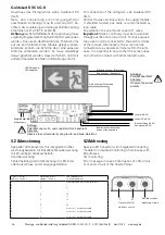
5.2 Elektrischer Anschluss GuideLed 10011 DX CG-S
5.2 Electrical wiring of the GuideLed 10011 DX CG-S
Weiße Leitung / white cable
Schwarze Leitung - / black cable -
Rote L / red cable +
Externer pot.-freier Kontakt
External volt-free contact
LED-Piktogramm
LED-pictogram
Achtung:
Polarität beachten!
Attention:
Observe the correct
polarity connection!
Netz- und Steuerleitung am Versorgungsmodul
anschließen.
Wichtiger Installationhinweis:
Die zulässige Leitungslänge am Steuereingang der
Leuchte ist abhängig von EMV-Einflüssen. Bei Nut-
zung einer ungeschirmten nicht verdrillten Leitung,
beträgt die maximale Leitungslänge ca. 2m.
Um die Leitungslänge zu erhöhen, wird die Nutzung
einer geschirmten und verdrillten Leitung mit einem
Mindestquerschnitt von 0,5mm² empfohlen, z.B. J-
Y(St)Y 2x2x0,8. Zum Schutz gegen elektrische Felder
wird empfohlen die Kabelabschirmung einseitig und
niederohmig (großflächig) mit der Betriebserde zu
verbinden. So können Leitungslängen von bis zu
50m erreicht werden. Die Verantwortung liegt beim
Errichter, mit einer korrekten Installation einen stö-
rungsfreien Betrieb herzustellen.
Connect mains and control wire to the supply module.
Important installation information:
The permissible cable length at the control input of
the luminaire depends on EMC influences. When
using an unshielded untwisted cable, the maximum
cable length is approx. 2m.
To increase the cable length, the use of a shielded
and twisted cable with a minimum cross-section of
0.5mm² is recommended, e.g. shielded and twisted
pair communication cable. To protect against electrical
fields, it is recommended to connect the cable shield
on one side and with low resistance (large area) to
the operating earth. This allows cable lengths of up
to 50m to be achieved. It is the responsibility of the
installer to ensure trouble-free operation with correct
installation.


