


56
4–20kVA Users Guide P-164000669 4–20kVA Users Guide P-164000669—Rev 09
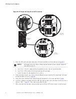
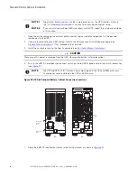
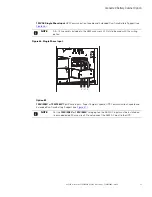
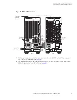
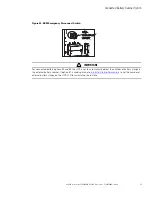
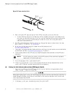
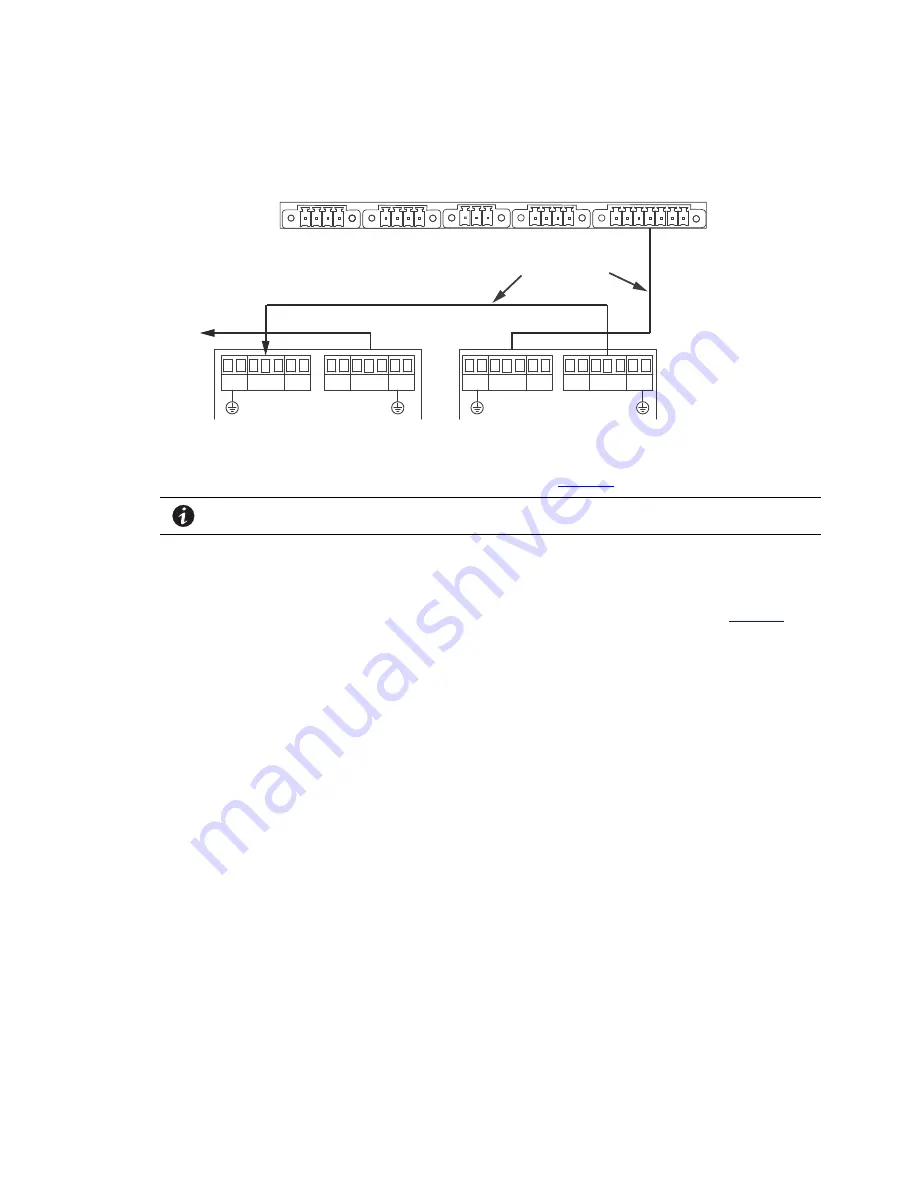
Figure 49. UPS Input Control Signal Wiring (For External Controls)
EPO
(CN7)
To EBM(s)
UPS
ROO and On Generator
(CN6)
External CAN
(CN4)
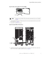
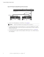
To previous (upstream)
EBM CN4
Signal cables and
connectors (supplied)
EBM 1
EBM 2
CAN OUT
(CN3)
CAN OUT
(CN3)
CAN IN
(CN4)
CAN IN
(CN4)
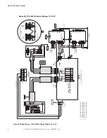
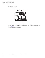
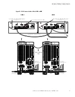
9.
Connect the CAN cable ground wires to the EBM chassis (see
).
NOTE
Connect each CAN ground wires to separate screws on the chassis.
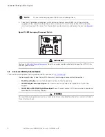
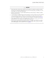
10. If an additional battery cabinet is to be connected to the first, in a daisy-chain configuration, use another
external battery cabinet cable assembly for the connections between the battery cabinets and connect as
per Step 1 to Step 9 above.
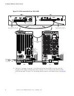
11. Install CAN communication wires between EBM to EBM and the EBM to UPS chassis (see
).
12. Install the green terminal jumper in to the spot labeled ‘Last EBM Jumper” in the last EBM of the daisey
chain configuration.
Summary of Contents for 9PXM
Page 1: ...p n P 164000669 Revision 09 Eaton 9PXM UPS 4 20kVA Users Guide Eaton 9PXM UPS ...
Page 4: ......
Page 8: ...viii 4 20kVA Users Guide P 164000669 4 20kVA Users Guide P 164000669 Rev 09 Table of Contents ...
Page 12: ...xii 4 20kVA Users Guide P 164000669 4 20kVA Users Guide P 164000669 Rev 09 List of Figures ...
Page 14: ...xiv 4 20kVA Users Guide P 164000669 4 20kVA Users Guide P 164000669 Rev 09 List of Tables ...
Page 22: ...8 4 20kVA Users Guide P 164000669 4 20kVA Users Guide P 164000669 Rev 09 Physical Features ...
Page 110: ...96 4 20kVA Users Guide P 164000669 4 20kVA Users Guide P 164000669 Rev 09 Communication Slots ...
Page 130: ...P 16400066909 P 164000669 09 ...