background image

8

4–20kVA Users Guide P-164000669 4–20kVA Users Guide P-164000669—Rev 09

Physical Features

Summary of Contents for 9PXM

Page 1: ...p n P 164000669 Revision 09 Eaton 9PXM UPS 4 20kVA Users Guide Eaton 9PXM UPS ...

Page 2: ...val of Eaton Class A EMC Statements FCC Part 15 NOTE This equipment has been tested and found to comply with the limits for a Class A digital device pursuant to part 15 of the FCC Rules These limits are designed to provide reasonable protection against harmful interference when the equipment is operated in a commercial environment This equipment generates uses and can radiate radio frequency energ...

Page 3: ...his symbol indicates that you should not discard the product in the trash This product must be disposed of properly For more information contact your local recycling reuse or hazardous waste center This symbol indicates that you should not discard waste electrical or electronic equipment WEEE in the trash For proper disposal contact your local recycling reuse or hazardous waste center IMPORTANT To...

Page 4: ......

Page 5: ...e Routing 24 3 5 System Wiring Diagrams 27 3 6 Bypass Overview 30 3 7 No Break Transfer from UPS Mode to Service Mode 31 3 8 Lock out Tag out 32 3 9 No Break Transfer from Service Bypass to UPS Mode 33 4 4 U UP PS S E Elle ec ct tr riic ca all I In ns st ta alllla at tiio on n 3 37 7 4 1 UPS Input Current Ratings 37 4 2 UPS Electrical Installation 39 4 3 System Wiring Diagram 43 5 5 B Ba at tt te ...

Page 6: ...tions 75 7 12 LCD Description 76 7 13 Display Status Indicators 76 7 14 Changing Parameter Settings 77 7 15 Display Menu Screens 77 8 8 C Co om mm mu un niic ca at tiio on n 9 91 1 8 1 Intelligent Power Manager 91 8 2 Optional Interface Kits 91 8 3 Communication Ports 91 8 4 Dedicated Input Signals 92 8 5 DB 9 Communication Port 94 8 6 Communication Slots 94 9 9 M Ma aiin nt te en na an nc ce e 9 ...

Page 7: ... 6 Output Run Times 103 10 7 Weights and Dimensions 103 10 8 Output Receptacles 104 10 9 Receptacle Circuit Breaker Ratings 105 1 11 1 T Tr ro ou ub blle es sh ho oo ot tiin ng g 1 10 07 7 11 1 Troubleshooting 107 11 2 Service and Support 110 1 12 2 W Wa ar rr ra an nt ty y 1 11 13 3 12 1 Two Year Limited Warranty 113 Table of Contents ...

Page 8: ...viii 4 20kVA Users Guide P 164000669 4 20kVA Users Guide P 164000669 Rev 09 Table of Contents ...

Page 9: ...nd Output Terminals 22 Figure 19 Bypass Switch Wiring Label and Terminal Blocks 23 Figure 20 UPS Input Control Signal Wiring for Maintenance Bypass 24 Figure 21 BPE to UPS Connector 25 Figure 22 Three Pin BPM to UPS Connector 25 Figure 23 Forced and Maintenance Bypass Screens 26 Figure 24 Wiring Diagram UPS with External Bypass Switch BPM L1 L2 N 28 Figure 25 Wiring Diagram UPS with External Bypas...

Page 10: ...Charger 63 Figure 55 Communication Ports 64 Figure 56 UPS Control Panel 75 Figure 57 LCD Display Status Indicators 76 Figure 58 Display Status Indicators 77 Figure 59 Start Screen 78 Figure 60 Status Screen Menu 78 Figure 61 Menu Screen 79 Figure 62 Measurements Menu 80 Figure 63 Control Menu 81 Figure 64 Local Setting Menu 82 Figure 65 In Out Settings Menu 83 Figure 66 On Off Settings Menu 84 Fig...

Page 11: ...4 20kVA Users Guide P 164000669 4 20kVA Users Guide P 164000669 Rev 09 xi Figure 81 Compatible Output Receptacles 104 Figure 82 Event Log Menu 107 List of Figures ...

Page 12: ...xii 4 20kVA Users Guide P 164000669 4 20kVA Users Guide P 164000669 Rev 09 List of Figures ...

Page 13: ...ble 3 Bypass Switch Positions 31 Table 4 BPM Dimensions 35 Table 5 UPS Recommended Breaker Sizes 38 Table 6 UPS Recommended Wire Sizes 38 Table 7 Electrical Input and Output 101 Table 8 Power Ratings 101 Table 9 Circuit Breaker Sizes 102 Table 10 Environmental and Safety 102 Table 11 Battery Ratings 103 Table 12 Weights and Dimensions 103 Table 13 Receptacle Circuit Breaker Ratings 105 ...

Page 14: ...xiv 4 20kVA Users Guide P 164000669 4 20kVA Users Guide P 164000669 Rev 09 List of Tables ...

Page 15: ...gh removable front panels All power modules share the load requirements equally For example three power modules are capable of supplying a total of 12 kVA If a load requires only 6 kVA each power module supplies 2 kVA to the output If one power module is removed or for some reason fails each of the two remaining power modules would supply half of the load or 3 kVA In other words redundancy exists ...

Page 16: ...l alimentation en entrée et en sortie pour l onduleur Ceux ci doivent se trouver dans le périmètre de l onduleur et être faciles d accès En ce qui concerne l unité de prise la prise sert d appareil de déconnexion de l alimentation en entrée laquelle doit également être facile d accès Advertencias de Seguridad INSTRUCCIONES DE SEGURIDAD IMPORTANTES GUARDE ESTAS INSTRUCCIONES Este manual contiene in...

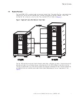
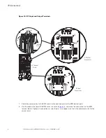
Page 17: ...r mounted UPS installation see Figure 1 Figure 1 Eight and Twelve Slot Cabinets Front View Caster Tray Control Panel Front Covers 8 Slot UPS 12 Slot UPS The rear UPS panel features power input and output connections with protective covers Communication ports provide input signals for maintenance bypass remote power off etc DB 9 USB ports and communication slots for network connectivity cards allow...

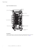
Page 18: ...Communication Ports Communication Card Slots DB 9 Port USB Port Knockout Recepticle Panels Twelve slot chassis shown Eight slot similar Power Modules UPS power modules UPMs are installed in the left hand slots of the UPS behind the front covers Battery slots consist of two battery modules each and can be used in both the right or left hand slots see Figure 3 Physical Features ...

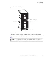
Page 19: ...e slot can contain up to eleven two battery slots Each two battery slot contains two battery modules that can be removed and installed separately from the battery slots in the chassis A battery module supplies 60VDC with five 12V batteries each 9PXM battery two battery slot supplies 120VDC with 10 batteries see Figure 4 NOTE You must install one 9PXM battery string Qty 2 battery modules in the mai...

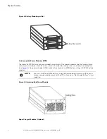
Page 20: ... to six modules Each 4kVA has a built in 5 amp battery charger and is cooled by two cooling fans see Figure 5 One power module UPM is able to fully charge five 9PXM battery strings 10 9PXM battery modules NOTE You must install one 9PXM battery string 2 battery modules in the main UPS chassis for every power module present or the UPS will sound an Not Enough Battery alarm indication Figure 5 Uninte...

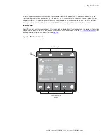
Page 21: ...ne in the lower left slot One super charger is able to fully charge 22 9PXM battery strings or 44 individual battery modules Control Panel The UPS control panel has a graphical LCD screen light indicators and function buttons It provides information and control for the UPS load status events measurements and settings Refer to 7 1 Normal Operation for control panel description and operation See Fig...

Page 22: ...8 4 20kVA Users Guide P 164000669 4 20kVA Users Guide P 164000669 Rev 09 Physical Features ...

Page 23: ...he back of the cabinet Do NOT attempt to move the cabinet with the power modules or battery modules installed External battery cabinets may be installed with bases tight against the UPS cabinet base and against each other 2 2 3 3 L Lo oc ca at tiio on n R Re eq qu uiir re em me en nt ts s Install the Eaton 9PXM UPS as close as possible to the equipment or the load distribution panel it will protec...

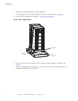
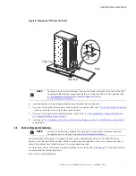
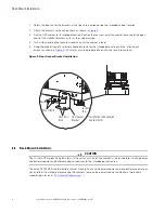
Page 24: ...e Figure 7 3 If you are rack mounting the UPS proceed to 2 6 Rack Mount Installation Figure 7 UPS on Shipping Pallet Caster Cart Leveling Feet 4 Bracket Bolts 8 4 Attach the supplied ramp to the pallet with the two brackets and four wood screws provided See Figure 8 5 Retract the leveling feet by turning them clockwise then carefully roll the cabinet down the ramp to its intended operating locatio...

Page 25: ...net continue to 5 1 Standard Battery Cabinet Installation or 5 2 Connected Battery Cabinet Option 9 Continue to 3 1 Installation of the UPS with an External Bypass Switch or 4 2 UPS Electrical Installation as applicable 2 2 5 5 A An nc ch ho or r B Br ra ac ck ke et t I In ns st ta alllla at tiio on n NOTE For ease of installation complete the rear electrical connections before securing the anchor...

Page 26: ...t as shown in Figure 9 All screws must be properly driven into the structural material Figure 9 Floor Anchor Bracket Installation Floor Anchor Bracket Floor Bolt Slots Mount Bolts Spacer Leveling Foot Installation to be updated spacers bolts 2 2 6 6 R Ra ac ck k M Mo ou un nt t I In ns st ta alllla at tiio on n CAUTION The 12 slot UPS weighs 93 kg 204 lb with the caster cart Install the cabinet in...

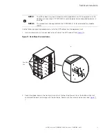
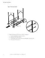
Page 27: ...002494 12 slot external battery module EBM Use the following mounting procedures to install the UPS cabinet into the equipment rack 1 Install rack mount ears two per side on each side of the UPS cabinet See Figure 10 Figure 10 Rack Mount Ear installation Rack Mount Ears 2 Select the proper holes in the front vertical rack rails that position the rack tray at the bottom in the rack and extend the b...

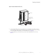
Page 28: ...UPS Rack Rails UPS Rack Rails Front 3 Remove the cabinet from the castor cart as follows see Figure 12 a Lower the leveling feet to stabilize the castor cart b Remove the rear bracket and screws c Using two people slide the cabinet backwards to disengage it from the slot tabs d Lift the cabinet off the caster cart Rack Mount Installation ...

Page 29: ...binet 4 Carefully slide the UPS from the caster tray onto the rail tray in the equipment rack until the rack mount ears of the cabinet are almost flush with the front vertical rails of the rack Install metal clip nuts in the rack in line with the upper mounting brackets Install the provided screws see Figure 13 5 Install the provided screws into the lower rack mount ears to the threaded holes in t...

Page 30: ...Rev 09 Figure 13 Securing the UPS in the Rack Screws Screws Rack Mount Ears Rail Tray Equipment Rack Rails 6 If you are installing an optional EBM cabinet refer to 5 1 Standard Battery Cabinet Installation or 5 2 Connected Battery Cabinet Option Rack Mount Installation ...

Page 31: ...as a licensed electrician should perform the electrical installation in this section NOTE For installation and configuration of the Eaton bypass switch refer to the manual Eaton Bypass Power Module BPM User s Guide P 164000628 supplied with the switch or on the Eaton website https www eaton com 9PXM If a bypass switch is used both UPS input and UPS output must be hardwired through separate conduit...

Page 32: ...e maximum allotted number of power modules no additional input ampacity will be required See Table 2 for recommended conductor sizes to wire the input circuit breakers Table 2 Recommended Wire Sizes Input Breaker Size 75 Copper Wire Size Conductor Screw Tourqe 25A 5 3 mm2 10 AWG 4 0 Nm 35 lb in 50A 8 4 mm2 8 AWG 4 5 Nm 40 lb in 80A 21 2 mm2 4 AWG 5 1 Nm 45 lb in 100A 33 6 mm2 2 AWG 6 6 Nm 50 lb in...

Page 33: ...overs The circuit breaker or disconnect switch must also be OFF at the AC input service panel To install the UPS with an external bypass switch 1 Mount the bypass switch within sight of the UPS If you do not have an Eaton bypass switch or the fuse box or panel is out of sight you must install a separate disconnect switch next to the UPS 2 The bypass switch should be mounted securely to a sturdy su...

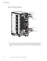
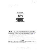
Page 34: ...ut Terminals Terminal Cover 5 At the AC Input terminal make sure to wire the UPS for the proper input voltage as shown in Figure 17 Split phase power modules provide a 2 phase output which can be configured as output voltages 110 110 for 220 120 120 for 240 120 120 for 208 or 127 127 for 220 Vac as selected through the front panel display UPS Connections ...

Page 35: ...l blocks on the rear panel see Figure 18 a Insert the L1 N and L2 cable ends into the applicable terminal slots on the terminal block b Insert the G GND cable end into the ground lug on the rear panel c Secure the cables by screwing down the lug screws d Torque the screws holding all input and output power conductors to the values specified in e Reinstall the AC and DC terminal covers CAUTION To r...

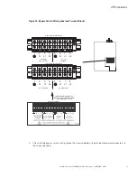
Page 36: ...1 AC Terminal Blocks Lug Screws Terminal Block Ground Lug 7 Route the power cables to the BPM and install conduit adapters to the BPM bottom plate 8 Use the label on the top of the BPM access cover and Figure 19 and make the connections to the BPM terminal blocks Tighten all connections as specified in Use copper wire that is the appropriate size for the current draw UPS Connections ...

Page 37: ...Terminal Block AC TO UPS INPUT L2 N L1 L2 N L1 AC TO LOADS CABLES FROM UPS AND AC INPUT OUTPUT THROUGH BPM BOTTOM ACESS PLATE AC FROM UPS OUTPUT L2 N L1 L2 N L1 Upper BPM Terminal Block Lower BPM Terminal Block AC LINE INPUT 9 After installing bypass switch wiring torque the screws holding all input and output power conductors to the values specified UPS Connections ...

Page 38: ...2 Place the signal wires through the proper conduit or grommet to the terminal block in the BPM Figure 20 UPS Input Control Signal Wiring for Maintenance Bypass AUX NO CONTACT NO CONTACT ON UPS white wire BYPASS NEUTRAL black wire FORCED BYPASS IN red wire External CAN to EBM CN4 Maintenance Bypass CN13 EPO CN7 3 2 1 4 3 2 1 4 3 2 1 4 3 2 1 7 6 5 4 3 2 1 Input signal wires ROO and On Generator CN6...

Page 39: ...ing the 3 pin connector see Figure 21 Figure 21 BPE to UPS Connector 3 2 1 4 3 2 1 4 3 2 1 4 3 2 1 7 6 5 4 3 2 1 Force Bypass Common On UPS FORCED BYPASS IN red wire BYPASS NEUTRAL black wire ON UPS white wire b Install the 3 pin connector into the 9PXM UPS BPM CN13 connector see Figure 22 Figure 22 Three Pin BPM to UPS Connector FORCED BYPASS IN red wire BYPASS NEUTRAL black wire ON UPS white wir...

Page 40: ...y settings Input Signals Comm Settings User Password Enable User Password setting Maintain Bypass Dry contact setting Enabled Polarity Normally open Efficiency 94 0 0 0kW 0 0kVA 100 19min 1EBM Load not powered 5 Install the supplied wiring connectors to the UPS input control signal wires and connect to the terminals as shown in or 6 When all connections have been made and checked reinstall the byp...

Page 41: ...cuit conductors including the neutral conductor must be the same size ampacity have the same rating 75 C copper wire and be sized according to the input circuit breaker See Table 2 The UPS input and output conductors must be run through separate conduits NOTE 4 The customer must provide output overcurrent protection See NEC Section 240 21 or local requirements See Table 1 for maximum output overcu...

Page 42: ...UT TO EBM 2 TO NEXT EBM If installed DC INPUT EBM 1 EBM 2 CN3 CN4 8 9 7 6 5 4 3 2 1 7 6 5 4 3 2 1 UPS CN4 EBM CN4 Supplied Connectors Pin numbering is right to left Input Signal connections Typical A A G N 1 L 2 L G L2 L1 N 110 220 Input 110 220 Output 120 208 Input 120 208 Output 120 240 Input 120 240 Output 127 220 Input 127 220 Output Force Bypass Red Wire Common Black Wire On UPS White Wire AU...

Page 43: ...PUT EBM 1 EBM 2 CN3 CN4 8 9 7 6 5 4 3 2 1 7 6 5 4 3 2 1 UPS CN4 EBM CN4 Supplied Connectors Pin numbering is right to left Input Signal connections Typical A A G L2 L1 N G L2 L1 N NO CONTACT Force Bypass Red Wire Common Black Wire On UPS White Wire 2 3 UPS s 9PXMSPPM split phase power modules and 1 Supercharger 9PXMCHGR or less installed in a 9PXM UPS Legacy Bypass 9PXM Compatibility 1 4 UPS s 9PX...

Page 44: ...d to the input terminals inside the UPS NOTE 3 If you have any questions or problems with the bypass operation call the Help Desk see 11 2 Service and Support The BPM consists of a load position handle and a red button see Figure 26 Figure 26 Bypass Switch Positions LOTO Bar red Interlock Button red Bypass switch handle The red button Sends an electrical signal to the UPS to switch to the internal...

Page 45: ...ever because SERVICE also disconnects AC input from the UPS this is the appropriate position for UPS maintenance or repair In the SERVICE position the UPS can be completely removed from the system 3 3 7 7 N No o B Br re ea ak k T Tr ra an ns sf fe er r f fr ro om m U UP PS S M Mo od de e t to o S Se er rv viic ce e M Mo od de e CAUTION Failure to understand the correct bypass sequence and position...

Page 46: ...nnected from AC power Ensure that the UPS is off and the terminals are completely de energized before performing any maintenance on the UPS Figure 28 Bypass From LINE to SERVICE Rotate switch to SERVICE position SERVICE MODE UTILITY LOAD BPM UPS FROM UPS TO UPS INPUT OUTPUT INPUT OUTPUT 3 3 8 8 L Lo oc ck k o ou ut t T Ta ag g o ou ut t The BPM comes with a Lock out Tag out LOTO feature to keep th...

Page 47: ...ce e B By yp pa as ss s t to o U UP PS S M Mo od de e After the system has been placed into SERVICE mode it must be returned to UPS state to resume normal operation WARNING It is critical that the following steps are followed to ensure correct and safe operation To turn the BPM to UPS mode 1 Turn the switch from SERVICE to LINE see Figure 30 The UPS is now in LINE mode and is energized It is often...

Page 48: ...l Bypass to UPS Normal mode online mode This transition may take as long as 60 seconds Figure 31 From LINE to UPS Rotate switch to UPS position UPS MODE UTILITY LOAD BPM UPS FROM UPS TO UPS INPUT OUTPUT INPUT OUTPUT 3 Once the switch is in UPS mode and the UPS is in Normal mode online mode the system is in normal operation and prepared to provide uninterrupted power to the critical load After turn...

Page 49: ...ress the button Control menu displays Press the button to select Go back normal Press the button to select Yes and press to return to normal UPS mode Press ESC twice to return to the Status Menu The UPS is now in Normal mode NOTE 1 The UPS should transfer from internal bypass to normal operation after a period of one minute automatically provided the Input signals are set correctly See Figure 23 N...

Page 50: ...36 4 20kVA Users Guide P 164000669 4 20kVA Users Guide P 164000669 Rev 09 No Break Transfer from Service Bypass to UPS Mode ...

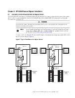
Page 51: ...is not used the UPS input may be hardwired through conduit to a main power source circuit breaker and the UPS output may either be hardwired to a circuit breaker in a distribution panel as shown in Figure 31 or supplied to loads through optional receptacles on the back of the UPS Without a bypass switch power to the load cannot be maintained if the UPS is taken completely offline Figure 32 Typical...

Page 52: ...ded Wire Sizes Input Breaker Size 75 Copper Wire Size Conductor Screw Tourqe 25A 5 3 mm2 10 AWG 4 0 Nm 35 lb in 50A 8 4 mm2 8 AWG 4 5 Nm 40 lb in 80A 21 2 mm2 4 AWG 5 1 Nm 45 lb in 100A 33 6 mm2 2 AWG 6 6 Nm 50 lb in 125A 42 1 mm2 1 AWG 6 6 Nm 50 lb in IMPORTANT FOR U S INSTALLATIONS READ THIS IMPORTANT NOTE lists the mm2 and AWG wire size for each circuit breaker size shown on the wiring diagrams...

Page 53: ...nt electrical shock or damage to the equipment verify that the Eaton 9PXM UPS is OFF before you remove the terminal covers The circuit breaker or disconnect switch must also be OFF at the AC input service panel To install the UPS without an external bypass switch 1 Install the AC terminal upper covers supplied in the accessory kit of the UPS See Figure 33 The AC input terminal block is located on ...

Page 54: ...als 2 At the AC Input terminal make sure to wire the UPS for the proper input voltage as shown in Figure 34 Split phase power modules provide a 2 phase output which can be configured as output voltages 110 110 for 220 120 120 for 240 120 120 for 208 or 127 127 for 220 Vac as selected through the front panel display 7 15 Display Menu Screens UPS Electrical Installation ...

Page 55: ...e 34 Split Phase Power Modules Split Phase Power Modules 3 wire plus ground input 2 PEN 110 220 120 208 120 240 127 220 Vac L2 N GND L1 NOTE UPS output circuits must be installed in separate conduit systems and not shared with other electrical circuits UPS Electrical Installation ...

Page 56: ...pplicable terminal slots on the terminal block b Insert the G GND cable end into the ground lug on the rear panel c Secure the cables by screwing down the lug screws 4 Route and connect the AC input cables to the building service panel and the AC output cables to the load distribution panel as shown in Figure 36 5 Torque the screws holding all input and output power conductors to the values specif...

Page 57: ... conductors including the neutral conductor must be the same size ampacity have the same rating 75 C copper wire and be sized according to the input circuit breaker See Table 6 for recommended wire sizes The UPS input and output conductors must be run through separate conduits NOTE 3 The customer must provide output overcurrent protection See NEC Section 240 21 or local requirements See Table 5 fo...

Page 58: ...20 240 Output 127 220 Input 127 220 Output INPUT OUTPUT POWER BUS BAR CN13 UPS NO AUX NO AUX NC 3 2 1 INPUT FROM FACILITY EXTERNAL DC AC OUTPUT AC INPUT UPS UPS INPUT SIGNALS CN3 CN4 CN6 CN6 CN4 5 6 AC INPUT TO EBM 1 AC INPUT TO EBM 2 TO NEXT EBM If installed DC INPUT EBM 1 EBM 2 CN3 CN4 CN3 CN4 7 A A G L2 L1 N G L2 L1 N 7 6 5 4 3 2 1 7 6 5 4 3 2 1 UPS CN4 EBM CN4 Supplied Connectors Pin numbering...

Page 59: ...vice circuit breaker or turn the external bypass switch to the SERVICE position Remove all battery modules in the UPS cabinet and or battery cabinet to ensure DC voltage is removed from the internal DC buses In the UPS cabinet the proper location of cabinet to cabinet DC wiring is on the lower left of the rear panel In the external battery cabinets P 103003632 and P 103003727 this wiring installs ...

Page 60: ...ee 2 6 Rack Mount Installation If not proceed to the next step 3 Install the anchor brackets to the floor if applicable see 2 5 Anchor Bracket Installation CAUTION Make sure all AC power is removed from the UPS Observe all electrical safety precautions 4 Push in the EBM DC emergency disconnect switch on the rear EBM panel and turn the switch lockout key see Figure 37 NOTE The UPS and EBM AC DC ter...

Page 61: ... Connect the EBM DC Cables to the applicable terminals by removing and reinstalling the screws onto the terminal blocks See Figure 40 3 Reinstall the AC and DC terminal covers Figure 40 Standard EBM to UPS Connections EBM Terminal Blocks UPS EBM Terminal Block From previous EBM if installed CN4 EBM UPS DC DC DC DC 4 If additional battery cabinets are to be connected to the first in a daisy chain c...

Page 62: ...trings on the UPS LCD for calculating the runtime 5 5 2 2 C Co on nn ne ec ct te ed d B Ba at tt te er ry y C Ca ab biin ne et t O Op pt tiio on n If you are not installing optional battery modules EBM continue to 6 1 UPS Startup The Advanced Battery Cabinet for the 9PX allows for the following enhanced installation options No AC Input Option For use for Extended Run Time Battery Support only 120V...

Page 63: ...t DC wiring is on the lower left of the rear panel In the external battery cabinets P 103002494 and P 103002725 this wiring installs into the rear panel where the DC emergency disconnect switch is located on the lower left of the rear panel See Figure 42 Do not connect the EBM AC input to the UPS output for the 120V 208V or 120V 240V Split Phase Input option the EBM must be installed on its own de...

Page 64: ...s Refer to the 2 1 Preparing for Installation section for unpacking and cabinet setup NOTE 2 If you are installing multiple EBM s upstream to the UPS repeat the setup as described in this section 1 Open the carton containing the external battery cabinet cable assembly and position it in the desired location next to the UPS 2 If you are rack mounting the EBM cabinet refer to the UPS rack mount inst...

Page 65: ...UPS and EBM accessory kit and do not come installed on the UPS or EBM chassis Figure 43 EBM to UPS Connections EBM Terminal Covers UPS DC Terminal Cover DC Emergency Disconnect Switch Communication Ports EBM UPS EBM Installation Wiring Options Connect the AC cables to the applicable terminals by inserting the ends into the AC terminal block and tighten the screws depending on the EBM configuration...

Page 66: ...e values specified in Table 2 2 Connect the EBM DC Cables to the applicable terminals by removing and reinstalling the screws onto the terminal blocks NOTE DC input cables only required if EBM s are installed upstream 3 Connect the AC cables to the applicable terminals by inserting the ends into the AC terminal block and tighten the screws depending on the EBM configuration option as follows Optio...

Page 67: ...ory kit Only to be used with this wiring option Figure 46 Single Phase Input G L1 N Option 3 120V 208V or 120V 240V Split Phase Input Super Charger Capable UPS Communication Capable and Extended Run Time Battery Support see Figure 47 NOTE For the 120V 208V or 120V 240V wiring option the EBM AC input must be installed on its own dedicated 30 amp circuit Do not connect the EBM AC input to the UPS Co...

Page 68: ...Phase Input G L1 N L2 4 Connect the AC ground cable into the ground lug and tighten the lug screw 5 Connect the EBM AC input cables to the dedicated 30 amp AC circuit and the DC output cables to the UPS See Figure 43 6 Reinstall the AC and DC terminal covers Connected Battery Cabinet Option ...

Page 69: ... AC supply for super charger if installed DC DC DC DC To UPS Signal Input Port CN4 L1 G N L2 7 On the upper rear panels connect the input signal cables from the EBM CN4 to the UPS input signal port CN4 using the supplied cables See Figure 43 8 If additional battery cabinets are to be connected to the first in a daisy chain configuration connect each EBM with signal cables from CN3 to CN4 see Figur...

Page 70: ...is see Figure 50 NOTE Connect each CAN ground wires to separate screws on the chassis 10 If an additional battery cabinet is to be connected to the first in a daisy chain configuration use another external battery cabinet cable assembly for the connections between the battery cabinets and connect as per Step 1 to Step 9 above 11 Install CAN communication wires between EBM to EBM and the EBM to UPS...

Page 71: ... 7 CN3 CN4 CANIN CANOUT LASTEBM JUMPER NOT FOR CUSTOMER USE RS 232 Secure Green and Yellow CAN cable ground wire to the chassis Secure Green and Yellow CAN cable ground wire to the chassis Green Terminal Jumper in Last EBM To UPS EBM 1 EBM 2 CN3 CN4 DC DC L1 G N L2 CN3 CN4 G L1 N L2 To UPS To next EBM AC input for super charger use AC input for super charger use DC DC G G EBM 2 EBM 1 Chassis Groun...

Page 72: ...SE RS 232 Secure Green and Yellow CAN cable ground wire to the chassis Green Terminal Jumper in Last EBM L1 G N L2 EBM 1 UPS Secure Green and Yellow CAN cable ground wire to the chassis Chassis Ground Wire 13 Close the DC emergency disconnect switch button on the back of each EBM Insert the switch key supplied with the cabinet into the button and turn clockwise 1 2 turn Pull the button OUT to clos...

Page 73: ...ch IMPORTANT For connected battery options 2 and 3 the UPS is set to automatically detect the number of battery strings in the external battery cabinet If option 1 is used continue to 6 5 Initial Startup Parameters to set the number of external battery strings on the UPS LCD for calculating the runtime Connected Battery Cabinet Option ...

Page 74: ...60 4 20kVA Users Guide P 164000669 4 20kVA Users Guide P 164000669 Rev 09 Connected Battery Cabinet Option ...

Page 75: ...uced if ambient temperature is higher Do NOT attempt to move the cabinet with the power or battery modules installed Power Module and Battery Module Installation The UPS power modules UPMs are installed in the left hand slots of the UPS facing the user Battery modules are installed in the left or right hand slots it takes two battery modules per slot to equal one battery string Removal of the powe...

Page 76: ...module Install the retaining bracket and tighten the captive screw with a Phillips screwdriver Figure 53 Inserting the Modules Captive Screws Power Module Front Covers 6 Retaining Bracket Battery Modules Captive Screw 5 If you installed the optional battery cabinets EBMs install the battery modules using the same procedure as the UPS modules If applicable install the super charger in the lower lef...

Page 77: ...ou ut t a an n E Ex xt te er rn na all B By yp pa as ss s S Sw wiit tc ch h To start the UPS unit for the first time after installation 1 If external battery cabinets EBMs are installed check the cable connections between the UPS and external battery cabinets see 5 1 Standard Battery Cabinet Installation or 5 2 Connected Battery Cabinet Option 2 Ensure that all power modules and battery modules ar...

Page 78: ...details 8 If there are receptacles on the UPS rear panel plug the equipment to be protected into the UPS output receptacles NOTE DO NOT protect laser printers with the UPS because of the exceptionally high power requirements of the heating elements 9 Turn on the equipment that is connected to the UPS 10 If there is an external bypass switch ensure a proper phase check has been completed then turn ...

Page 79: ...ure the voltage between the following points on the terminal block and record in the spaces below These measurements must be no more than 20 Vac if they are call your service representative Terminal 3 AC From UPS Output To Terminal 7 AC To UPS Input Terminal 4 AC From UPS Output To Terminal 8 AC To UPS Input 9 Measure the AC voltage between the following points on the terminal block and record in ...

Page 80: ...panel or verify that the load cannot receive power from the UPS 2 At the bypass switch press the red button and turn the switch to UPS 3 Remove the six screws in the bypass switch front cover and remove the cover to gain access to the terminal block for voltage measurements 4 If external battery cabinets are installed close the DC emergency disconnect switch button on the back of each external bat...

Page 81: ...ternal battery cabinet closest to the UPS Otherwise continue to Step 14 14 When starting the UPS apply input power to the UPS by closing the service circuit breaker l If external battery cabinets are installed close the DC emergency disconnect switch button on the back of each external battery cabinet Insert the switch key supplied with the cabinet into the button and turn clockwise 1 2 turn Pull ...

Page 82: ...M DD YYYY US Format 02 05 2020 03 05 Date Time International Format 23 05 2020 15 05 Date Time MM DD YYYY US Format 02 05 2020 03 05 Settings Event Log Fault Log Identification Register Product Menu Please register at www eaton com Type Eaton 9PXM Date Time International Format 23 05 2020 15 05 Date Time MM DD YYYY US Format 02 05 2020 03 05 4 Select Register product from the menu and register you...

Page 83: ...nal battery strings that you have installed See 5 1 Standard Battery Cabinet Installation or 5 2 Connected Battery Cabinet Option 8 The UPS is now ready to operate and displays the normal On Off function screen Press the ON button on the display screen to start the UPS Online mode 100 19min 1EBM 100 2 7kW 3 0kVA Efficiency 94 NOTE These configuration parameters are accessible during normal UPS ope...

Page 84: ...70 4 20kVA Users Guide P 164000669 4 20kVA Users Guide P 164000669 Rev 09 Initial Startup Parameters ...

Page 85: ...wered and protected 7 Make sure the UPS is in Online mode 7 7 2 2 U UP PS S S St ta an nd db by y M Mo od de e To place the UPS in standby Press the button on the front panel for three seconds The UPS starts to beep then transfers to Standby mode The indicator will flash continually 7 7 3 3 U UP PS S S Sh hu ut td do ow wn n CAUTION Observe all Lock Out Tag Out procedures when external power is re...

Page 86: ...kup Time All the LEDs go OFF The audio alarms stops 7 7 4 4 3 3 L Lo ow w B Ba at tt te er ry y W Wa ar rn niin ng g During discharge the low battery alarm is activated if the remaining runtime goes below 3 minutes or less than the setting capacity threshold 0 by default This threshold can be modified 7 7 4 4 4 4 B By yp pa as ss s M Mo od de e Bypass Mode In the event of a UPS overload or interna...

Page 87: ...t tiin ng gs s The following settings are available for configuring Bypass operation see Figure 65 CAUTION Changing the Bypass settings changes UPS behavior and may result in decreased protection Bypass Voltage Min Limit The default disables a transfer to Bypass if the measured bypass voltage level is below the nominal output voltage 12 You can configure the setting for another voltage value This ...

Page 88: ... te er ry y W Wa ar rn niin ng g During discharge the low battery alarm is activated if the remaining runtime goes below 3 minutes or less than the setting capacity threshold 0 by default This threshold can be modified 7 7 7 7 4 4 E Ex xt te er rn na all B Ba at tt te er ry y S Se et tt tiin ng g The number of Extended Battery Module is automatically detected or can be set manually in number of EB...

Page 89: ...scape Up Down Enter On Off button 7 7 1 11 1 D Diis sp plla ay y F Fu un nc ct tiio on ns s Press the Enter button to activate the menu options Use the two middle buttons and to scroll through the menu structure Press the Enter button to select an option Press the ESC button to cancel or return to the previous menu see Figure 49 Indicator Status Description Green On The UPS is operating normally o...

Page 90: ... saver The LCD backlight automatically dims after 10 minutes of inactivity Press any button to restore the screen Figure 57 LCD Display Status Indicators Online mode 100 19min 1EBM 100 2 7kW 3 0kVA Efficiency 94 Efficiency and load group information Battery status Load equipment status Operation status 7 7 1 13 3 D Diis sp plla ay y S St ta at tu us s I In nd diic ca at to or rs s The following ta...

Page 91: ...y 0 100 Runtime 0mn 60mn The alarm triggers when the set percentage of battery capacity or remaining back up time is reached High Efficiency Mode The UPS is operating on High Efficiency mode The UPS is powering and protecting the equipment Bypass Mode An overload or a fault has occurred or a command has been received and the UPS is in Bypass mode Equipment is powered but not protected by the UPS 7...

Page 92: ...The status screen shows the status of the installed units Figure 60 Status Screen Menu 100 100 10 1kW 10 min 10 1kV 24 Press to start UPS 4 1 6 4 EBM EBM 1 1 5 EBM 2 1 5 EBM 3 1 6 EBM 4 1 2 Menu Screen The Menu Screen selects and controls system features and operating conditions see Figure 54 Menu items include Measurements Control Settings Event Log Fault Log Identification Registration Informati...

Page 93: ...VA Users Guide P 164000669 Rev 09 79 Figure 61 Menu Screen Menu Measurements Control Settings Event Log Identification Register Product Measurements The Measurements screen shows the measurements of the installed units Display Menu Screens ...

Page 94: ...al Load Load Phase 1 N L1 Load Phase 2 N L2 Input Bypass Measurements Total Output Load Phase 2 N L2 Input Bypass Output Efficiency Measurements Output Efficiency Input Bypass Total Output Battery Measurements Battery Bypass Total Output Output Efficiency Average power usage Measurements Average power usage Total Output Output Efficiency Battery Cumulat power usage Total Load 0W 0 0A 0VA 0 00pf Lo...

Page 95: ...tate Restore factory set Reset average power Control Go to bypass Start battery test Reset fault state Restore factory set Reset average power Control Go to bypass Start battery test Reset fault state Restore factory set Reset average power Control Reset Cumul power Start battery test Reset fault state Restore factory set Reset average power Control Go to bypass Start battery test Reset fault stat...

Page 96: ...ssword settings Settings Local settings Language Date time LCD Audible alarm LCD settings Audible alarm Enabled Disable on battery Always disabled English Français Espanol Menus status notices and alarms UPS fault Event Log data and settings are in all supported languages Format International US Set Time to International format Drop down menu to select format Set Time to US format Modify LCD Modif...

Page 97: ... Disabled Enabled Protected Bypass Enabled Disabled Overload prealarm 100 Byp freq limit Byp volt min limit Byp volt max limit Redundancy Level 0 Level 1 Level 2 Level 3 Level 4 4 Hz 12 12 110V 120V 127V Default 120V 127V Enabled Disabled Power the output from Default Disabled Enabled Disabled Default Enabled 10 102 Load when overload alarm occurs Default 100 Set redunancy level Default 0 Default ...

Page 98: ... 1000 W 1500 W 2000 W Select On Off Settings Auto restart Enabled Disabled Site Wiring Fault Disabled Enabled Shut off level Enabled Disabled Timer 10s 180s When mains recover during a shutdown sequence If set to Enabled shutdown sequence will complete and wait 10 seconds prior to restart If set to Disabled shutdown sequence will not complete UPS stays on Default Value Enabled Enabled Disabled Ena...

Page 99: ...al battery Auto Detection Auto Detection Manual EBM set Manual batt set External battery Auto Detection 1 BM External battery Manual EBM set 0 Strings External battery Manual batt set 0 AH Advanced Battery Mode Enabled Disabled In ABM cycling mode No test Every ABM cycle In constant charge mode No test Every day Every week Every month Default Value Every ABM cycle Every week Capacity 0 100 Runtime...

Page 100: ...able User password settings Settings Emergency power off Remote On Off On Generator Force Bypass Maintain Bypass Input Signals Emergency Power Off Enabled Disabled Remote On Off Disabled Normally Open On Generator Disabled Normally Open Force Bypass Disabled Normally Open Maintain Bypass Disabled Normally Open Select Input Signals Enabled Disabled Normally open Enabled Disabled Normally open Enabl...

Page 101: ...wn command Battery notice delay Comm Settings Com Settings Send command Output off Off delay 10s Output off Minislot 2 remote off Minislot 2 remote off Comm Settings Minislot 2 reset Minislot 1 reset ABM On Off Minislot 2 remote off Remote command Shutdown command Battery notice delay Minislot 1 reset Minislot 2 reset Battery settings Minislot 1 remote off Yes No Yes No 0s 99s Sets delay before di...

Page 102: ...entification Register Product Menu Event Log Event filter Event list Reset event list Event Log Event filter Event list Reset event list Event Log Event filter Event list Reset event list 09 26 2017 09 28 27 Event Log Display faults Display alarms Display events Event Log 09 26 20 09 28 ABM Off 09 26 20 09 28 Line Converter Event Log 09 26 20 09 28 ABM Off 09 26 20 09 28 Line Converter Reset event...

Page 103: ...nance bypass No Identification Product type model Part Serial number UPS NMC firmware CSB EBM firmware Com card IPv4 Identification Product type model Part Serial number UPS NMC firmware CSB EBM firmware Com card IPv4 Identification Product type model Part Serial number UPS NMC firmware CSB EBM firmware Com card IPv4 Identification Product type model Part Serial number UPS NMC firmware CSB EBM fir...

Page 104: ...ith Eaton Figure 74 Register Product Menu Date Time International Format 23 05 2020 15 05 Date Time MM DD YYYY US Format 02 05 2020 03 05 Date Time International Format 23 05 2020 15 05 Date Time MM DD YYYY US Format 02 05 2020 03 05 Settings Event Log Fault Log Identification Register Product Menu Please register at www eaton com Type Eaton 9PXM Display Menu Screens ...

Page 105: ... uptime and data integrity by allowing the user to remotely monitor manage and control UPSs and other devices on their network IPM provides a solution that is easy to use and maintains business continuity 8 8 2 2 O Op pt tiio on na all I In nt te er rf fa ac ce e K Kiit ts s For computer systems that already have UPS monitoring software Eaton offers interface cable kits for connecting the Eaton 9P...

Page 106: ... slot select external CAN signals to next EBM Last EBM Jumper DB 9 RS 232 port USB port Figure 76 EBM Communication Port CN5 DB 9 Communication Port CN12 USB Communications Port CN3 CN4 CN6 Refer to detail A in for the type of signal connectors used 8 8 4 4 D De ed diic ca at te ed d I In np pu ut t S Siig gn na alls s Dedicated Input Signals Emergency Power off EPO Connection to a facility Emerge...

Page 107: ...should be connected to Pins 1 and 2 and should be closed during normal operation of the UPS see Figure 78 Figure 78 EPO Normally Closed Connections REPO Switch NO Twisted Wires 1 3 REPO TB 2 4 2 1 NOTE REPO switch rating is 24 Vdc 1A minimum NOTE The REPO switch must be a latching type switch not tied to any other cicuits Maintenance Bypass The signal from an external bypass switch to isolate the ...

Page 108: ...he UPS detects an AC Failure condition assuming the condition still exists after the 15 seconds When the AC Failure condition no longer exists the signal returns to the RS 232 Low state positive voltage 9 No Connection DC Supply Voltage The UPS is factory set with Pin 9 disconnected but can be enabled through a technician replaceable jumper inside the UPS The jumper setting MUST be changed by a qu...

Page 109: ...MODBUS Card MS combines an SNMP agent HTTP Web server and a MODBUS card facilitating UPS supervision from any network monitoring system using SNMP and traps or any web browser Relay Card MS The Eaton Relay Card MS enables automatic shutdown and network monitoring of UPS system status through a connected computer with a dedicated adapter that provides the essential dry contact interface between an ...

Page 110: ...96 4 20kVA Users Guide P 164000669 4 20kVA Users Guide P 164000669 Rev 09 Communication Slots ...

Page 111: ... 4 to 104 F Batteries will have a longer shelf life if they are kept below 25 C 77 F The Eaton 9PXM UPS or battery cabinet without batteries may be stored at 40 to 60 C 40 to 140 F 9 9 3 3 E Ex xt te er rn na all B By yp pa as ss s S Sw wiit tc ch h M Ma ak ke e B Be ef fo or re e B Br re ea ak k O On nlly y O Op pe er ra at tiio on n Press the red button beside the switch before turning the Eaton...

Page 112: ... for your warranty 5 Insert the replacement battery modules by sliding the lower module carefully into the cabinet Repeat for the upper replacement module 6 Reinstall the retaining bracket and tighten the captive screw 7 Replace the front cover Figure 79 Battery Replacement Retaining Bracket Battery Modules Captive Screw Front Covers 9 9 5 5 P Po ow we er r M Mo od du ulle e R Re ep plla ac ce em ...

Page 113: ...dules with masking tape or some other identifier Record the serial number of the replacement power modules for your warranty 4 Insert the replacement power module by sliding it carefully into the cabinet 5 Tighten the captive screws to the UPS cabinet 6 Replace the front cover Figure 80 Power Module Replacement Captive Screws Power Module Front Covers 9 9 6 6 U UP PS S F Fiir rm mw wa ar re e U Up...

Page 114: ...100 4 20kVA Users Guide P 164000669 4 20kVA Users Guide P 164000669 Rev 09 UPS Firmware Upgrade ...

Page 115: ...t frequency to selectable limit 0 1 to 5 0 Hz 3 0 Hz default switches to battery operation outside this tolerance On battery 60 Hz 0 1 Hz Regulation 5 load regulation under any line load or battery condition Voltage Waveform Sine wave 5 THD at rated linear loads computer grade power Overload Capability 115 for 3 seconds 115 for 12 cycles DC Input Protection DC fuse Output Protection Microprocessor...

Page 116: ...nm me en nt ta all a an nd d S Sa af fe et ty y Table 10 Environmental and Safety Operating Temperature 0 C to 40 C 32 F to 104 F Optimal battery performance 25 C 77 F Storage Temperature UPS with battery modules 20 C to 40 C 4 F to 104 F UPS without batteries 40 C to 60 C 40 F to 140 F Relative Humidity 5 95 noncondensing Operating Altitude Up to 3 050 meters above sea level 10 000 ft The maximum...

Page 117: ...ting Nominal Input Connection Output See Output Receptacles Figure 74 Minimum Run time at full power load Split Phase 20kVA 12 Slot 110 220 120 208 120 240 18000 16200 20000 18000 20000 18000 20000 18000 Hardwired Hardwired Optional Receptacles 5 8 min Split Phase 16kVA 8 Slot 110 220 120 208 120 240 16000 14400 Hardwired Hardwired Optional Receptacles 5 8 min 1 10 0 7 7 W We eiig gh ht ts s a an ...

Page 118: ... lb Super Charger 29 2 cm 11 5 68 6 cm 27 5 38 1 cm 15 12 5 kg 27 5 lb 15 2 cm 6 58 4 cm 23 21 6 cm 8 5 10 2 kg 22 5 lb N A Rail Kit 26 7 cm 10 5 101 6 cm 40 61 cm 27 4 kg 60 5 lb 14 cm 58 4 cm 23 49 5 cm 19 5 15 6 kg 34 5 lb N A 24 5 5 Caster 25 4 cm 10 101 6 cm 40 61 cm 28 1 kg 62 lb 12 7 cm 5 73 7 cm 29 50 8 cm 20 16 3 kg 36 lb N A 24 Floor anchor kit 20 3 25 4 cm 10 15 2 kg 6 4 1 kg 9 lb 12 7 ...

Page 119: ...er r R Ra at tiin ng gs s Table 13 Receptacle Circuit Breaker Ratings Receptacle Panel Circuit Breaker Quantity per Panel 20 May 1 Pole 20 Amp 2 IEC60309 2 Pole 30 Amp 1 C13 2 Pole 20 Amp 2 C19 2 Pole 30 Amp 2 L14 30 2 Pole 30 Amp 2 L5 20 1 Pole 20 Amp 2 L5 30 1 Pole 30 Amp 2 L6 20 2 Pole 20 Amp 2 L6 30 2 Pole 30 Amp 2 Receptacle Circuit Breaker Ratings ...

Page 120: ...106 4 20kVA Users Guide P 164000669 4 20kVA Users Guide P 164000669 Rev 09 Receptacle Circuit Breaker Ratings ...

Page 121: ...1 Press any button on the front panel display to activate the menu options 2 Press the down arrow button to select Event log or Fault log from the Menu screen Figure 82 Event Log Menu Control Measurements Settings Event Log Fault Log Identification Register Product Menu Event Log Event filter Event list Reset event list Event Log Event filter Event list Reset event list Event Log Event filter Even...

Page 122: ...ct your service representative The UPS does not provide the expected backup time The batteries need charging or service Apply utility power for 48 hours to charge the batteries If the condition persists contact your service representative Bypass Mode LED is On An overload or a fault has occurred or a command has been received and the UPS is in Bypass mode Equipment is powered but not protected by ...

Page 123: ...gged into the cabinet and each module secured in it s slot If external battery cabinets are installed confirm that the DC emergency disconnect switch button on the back of the cabinet is closed pulled out To close the DC emergency disconnect switch button insert the switch key supplied with the cabinet into the button and turn clockwise 1 2 turn Pull the button out to close the switch Turn the key...

Page 124: ...the menu in Figure 65 Change the batteries Each pair of battery modules of a two battery slot forms one series slot on the battery bus See 9 4 Battery Replacement for the battery replacement procedure Add delete one or more slots of batteries Physically install or remove battery modules as described in 9 4 Battery Replacement If not using a 9PXM EBM record the capacity of external battery slots in...

Page 125: ...ppear on the outside of the package and on the Bill Of Lading if applicable Use the original packaging or request packaging from the Help Desk or distributor Units damaged in shipment as a result of improper packaging are not covered under warranty A replacement or repair unit will be shipped freight prepaid for all warrantied units NOTE For critical applications immediate replacement may be avail...

Page 126: ...112 4 20kVA Users Guide P 164000669 4 20kVA Users Guide P 164000669 Rev 09 Service and Support ...

Page 127: ...st ship to Company the defective Warranted Item the following procedures are required If the Warranted Item is to be replaced by Company and the End user supplies a credit card number or purchase order for the value of the replacement product Company will use commercially reasonable business efforts to ship via standard ground shipment and at no cost to the End user the replacement Warranted Item ...

Page 128: ...Y FOR FAILURE OF COMPANY TO MEET ITS WARRANTY OBLIGATIONS WHETHER CLAIMS OF THE END USER ARE BASED IN CONTRACT IN TORT INCLUDING NEGLIGENCE OR STRICT LIABILITY OR OTHERWISE LIMITATION OF LIABILITY The remedies of the End user set forth herein are exclusive and are the sole remedies for any failure of Company to comply with its obligations hereunder In no event shall Company be liable in contract i...

Page 129: ...sly provided for by the terms of this Warranty including without limitation site calls involving an inspection that determines no corrective maintenance is required Any costs for replacement equipment installation materials freight charges travel expenses or labor of Company representatives outside the terms of this Warranty will be borne by the End user Two Year Limited Warranty ...

Page 130: ...P 16400066909 P 164000669 09 ...

Reviews: