

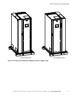


UPS System Installation
Eaton 93PM UPS (20–50 kW, 480V Four Wire – 50 kW Frame) Installation and Operation Manual P-164000540—Rev 4
www.eaton.com/powerquality
4-11
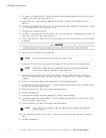
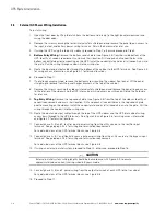
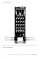
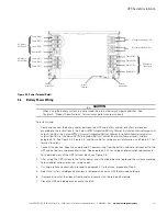
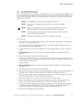
Figure 4-8. Power Terminal Detail
4.6
Battery Power Wiring
CAUTION
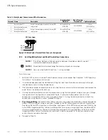
When sizing the battery system, do not exceed the internal battery charger capabilities. See
Chapter 9, “Product Specifications,” for maximum battery charger currents.
To install wiring:
1.
Route and connect the battery cables between the UPS and battery cabinet or battery disconnect
according to the instructions in the
Eaton 93PM Integrated Battery Cabinet Installation Manual-Large and
Large High Rate
, the
Eaton 93PM Universal Integrated Battery Cabinet Installation Manual-Large and
Large High Rate
, or the
Eaton 93PM Integrated Battery Cabinet Installation Manual-Small
, listed in
paragraph 1.8. See Figure 4-4, Figure 4-5, and Figure 4-6 for wiring access information, and Figure 4-7 for
terminal locations.
2.
Connect the positive, negative, and ground DC power wiring from the battery cabinet or disconnect to the
UPS cabinet battery and ground terminals. See paragraph 3.2.2 for wiring and termination requirements.
For a detailed view of the UPS terminal block, see Figure 4-8.
3.
After wiring the UPS system to the facility power and critical load, be sure to ground the system according
to local and/or national electrical wiring codes.
4.
If wiring interface connections, proceed to paragraph 4.7; otherwise, proceed to Step 5.
5.
Reinstall all safety shield panels previously removed and secure with the retained hardware.
6.
If removed, reinstall the sidecar front panel and secure with the retained hardware.
7.
Close the UPS outside door and secure the latch.
Phase A (E6)
Phase B (E7)
Phase C (E8)
Phase C (E3)
Phase B (E2)
Phase A (E1)
Neutral (E12)
AC Input to
UPS Bypass
AC Input to
UPS Rectifier
DC Input from Battery - (E5)
DC Input from B (E4)
AC Output to
Critical Load
Phase C (E11)
Phase B (E10)
Phase A (E9)
Neutral (E12)
Cabinet
Ground Post
Cabinet
Ground Post
Ground
Terminals
Summary of Contents for 93PM UPS
Page 1: ...Eaton 93PM UPS 20 50 kW 480V Four Wire 50 kW Frame Installation and Operation Manual...
Page 2: ......
Page 3: ...Eaton 93PM UPS 20 50 kW 480V Four Wire 50 kW Frame Installation and Operation Manual...
Page 25: ...Section 1 Installation...
Page 26: ......
Page 87: ...Section 2 Operation...
Page 88: ......
Page 145: ......
Page 146: ...P 164000540 4 P 164000540 4...


