


UPS Installation Plan and Unpacking
3-20
Eaton 93PM UPS (20–50 kW, 480V Four Wire – 50 kW Frame) Installation and Operation Manual P-164000540—Rev 4
www.eaton.com/powerquality
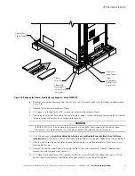
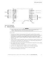
3.2.4
UPS System Interface Wiring Preparation
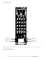
Control wiring for features and options should be connected at the customer interface terminal blocks located
inside the UPS.
WARNING
Do not directly connect relay contacts to the mains related circuits. Reinforced insulation to the
mains is required.
Read and understand the following notes while planning and performing the installation:
l
Use Class 1 wiring methods (as defined by the NEC) for interface wiring from 30V to 600V. The wire should
be rated for 600V, 1A minimum. 12 AWG maximum wire size.
l
Use Class 2 wiring methods (as defined by the NEC) for interface wiring up to 30V. The wire should be rated
for 24V, 1A minimum.
l
Because of the battery shunt trip wiring route in the UPS cabinet, the wire should be rated for a minimum of
600V.
l
Use twisted-pair wires for each input and return or common.
l
All interface wiring and conduit is to be supplied by the customer.
l
When installing external interface wiring between a building alarm, relay output, battery breaker trip, or
Minislot and the UPS interface terminals, conduit must be installed between each device and the UPS
cabinet.
l
If using conduit, install the interface wiring in separate conduit from the power wiring.
l
All building alarm inputs require an isolated normally-open contact or switch (rated at 24 Vdc, 20 mA
minimum) connected between the alarm input and common terminal. All control wiring and switch contacts
are customer-supplied.
l
LAN and telephone drops for use with Minislot connectivity cards must be supplied by the customer.
l
The UPS battery detect signal wiring from an UPS building alarm must be connected to the battery
disconnect device.
l
Program the battery detect building alarm to read battery open and for normally open contacts.
l
A supplemental 48 Vdc shunt trip signal for the battery disconnect device is provided, but is not required for
normal operation.
l
Battery detect and 48 Vdc shunt trip wiring should be a minimum of 18 AWG.
l
The REPO feature opens all switchgear in the UPS cabinet and isolates power from your critical load. Local
electrical codes may also require tripping upstream protective devices to the UPS.
l
The REPO switch must be a latching-type switch not tied to any other circuits.
l
A jumper wire must be connected between pins 3 and 4 on the REPO terminal block if using a
normally-closed REPO switch.
l
REPO wiring should be a minimum of 18 AWG and a maximum of 16 AWG.
l
The REPO switch wiring must be in accordance with NEC Article 725 Class 2 requirements.
l
The maximum distance between the REPO and the UPS cannot exceed 150m (500 ft).
NOTE
Refer to the
Eaton 93PM Sidecar Integrated Accessory Cabinet-Bypass Installation
and Operation (50 kW and 100 kW SIAC-B) Manual
, listed in paragraph 1.8, for
SIAC-B power wiring preparation and requirements.
Summary of Contents for 93PM UPS
Page 1: ...Eaton 93PM UPS 20 50 kW 480V Four Wire 50 kW Frame Installation and Operation Manual...
Page 2: ......
Page 3: ...Eaton 93PM UPS 20 50 kW 480V Four Wire 50 kW Frame Installation and Operation Manual...
Page 25: ...Section 1 Installation...
Page 26: ......
Page 87: ...Section 2 Operation...
Page 88: ......
Page 145: ......
Page 146: ...P 164000540 4 P 164000540 4...


