


UPS System Installation
4-4
Eaton 93PM UPS (20–50 kW, 480V Four Wire – 50 kW Frame) Installation and Operation Manual P-164000540—Rev 4
www.eaton.com/powerquality
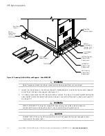
14. If a sidecar is attached to the UPS, remove the sidecar mounting bolts holding the front and rear sidecar
supports to the cabinet base (see Figure 4-2).
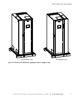
15. Remove the cabinet mounting bolts holding the front and rear supports to the cabinet base (see
16. If installing the cabinet permanently, retain the cabinet mounting bolts; otherwise, recycle the bolts along
with the support brackets in a responsible manner.
17. Close the door and secure the latch.
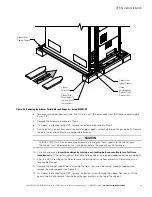
18. If a sidecar is attached to the UPS, remove the screws securing sidecar rear shipping bracket. Remove the
bracket and reinstall the screws (see Figure 4-3).
19. If the leveling feet are not retracted, turn all four leveling feet until they are retracted as far into the cabinet
as possible.
CAUTION
To prevent tipping when rolling the cabinet, push the cabinet from the rear whenever possible.
20. Roll the cabinet to the final installation location.
21. Secure the UPS in position by lowering the leveling feet until the cabinet is level and locked in place.
22. If permanently mounting the UPS using the left and right side floor mounting brackets, proceed to
Step 23; if using the front and rear floor mounting brackets, proceed to Step 27; otherwise, proceed
to Step 30.
23. Locate the left and right side floor mounting brackets from the floor mounting kit.
24. Using the retained cabinet mounting bolts, install the floor mounting brackets to the left and right side of
the UPS with the angle facing outward.
25. Secure the cabinet to the floor with customer-supplied hardware.
26. Proceed to paragraph 4.3.
27. Locate the front and back floor mounting brackets from the floor mounting kit.
28. Using the retained cabinet mounting bolts, install the floor mounting brackets to the front and rear of the
UPS with the angle facing outward.
29. Secure the cabinet to the floor with customer-supplied hardware.
30. Locate the black cover dots from the parts kit and install over the left and right side bracket mounting
holes.
31. Proceed to paragraph 4.3.
NOTE
Use the leveling feet to level and lock the cabinet in place.
NOTE
Either front and back floor mounting brackets or left and right side floor mounting
brackets are available for permanently mounting the UPS.
NOTE
Black cover dots are provided, if side mounting bracket holes need to be covered for
aesthetic reasons.
Summary of Contents for 93PM UPS
Page 1: ...Eaton 93PM UPS 20 50 kW 480V Four Wire 50 kW Frame Installation and Operation Manual...
Page 2: ......
Page 3: ...Eaton 93PM UPS 20 50 kW 480V Four Wire 50 kW Frame Installation and Operation Manual...
Page 25: ...Section 1 Installation...
Page 26: ......
Page 87: ...Section 2 Operation...
Page 88: ......
Page 145: ......
Page 146: ...P 164000540 4 P 164000540 4...


