46 Maintenance
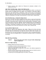
7. Check conveyor chain tension by following the procedure outlined in the
Adjustments section.
Idler, Roller Shaft, Bearings, or Sprockets Replacement
Refer to the preceding Roller Silicone Covering Replacement section to access and
remove rollers as required. Note the location and orientation of sprockets (make a
sketch and note measurements if necessary). Loosen the jam nuts on the tensioning
bolts at the drive end of the conveyor. Remove the four (4) ¼-20 bolts for the bearings.
Slide the shaft left or right and then the shaft and sprockets will come off. Identify and
replace any damaged or worn parts and reassemble in reverse order of disassembly.
Drive Shaft, Bearings, or Sprockets Replacement
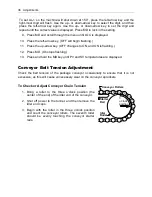
Refer to the Conveyor belt tension adjustment section above to open up the conveyor
belt. Remove the drive end caps. Disconnect the conveyor belt. Note the location and
orientation of sprockets (make a sketch and note measurements if necessary). Loosen
four (4) set screws on the drive sprockets. Keep the keyway key for the driveshaft and
replace as necessary. Slide the shaft left or right. The shaft sprockets must be adjusted
for position. All sprockets are fastened to the shaft by set screws. Identify and replace
any damaged or worn parts and reassemble in reverse order of disassembly.
Conveyor Motor Replacement
Shut off the machine and disconnect main power. Remove the drive end cap,
disconnect two (2) electrical wires from the drive motor, and disconnect the motor from
the drive chain by removing four (4) bolts that hold the drive motor. Remove the
sprocket from the old motor and place it on the new drive motor and reassemble parts in
the same as they were disassembled. For electrical connections, refer to the electrical
schematics.
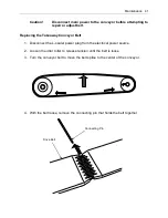
Wire Belt Repair Splicing
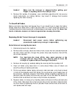
Caution!
Disconnect main power to the conveyor before attempting to
repair or adjust belt.
Before You Begin Splicing
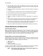
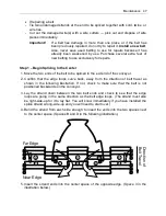
Release all belt tensioning mechanisms.
If installing a new belt, thread the belt onto the conveyor.
-
Check to be sure that the smooth side is “up.”
- Check to be sure that the edge loops curve back in the direction opposite the
direction of belt travel.
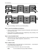
- Remove a strand or two from the new belt to keep in reserve to splice the belt or
in case it may be needed to repair the belt in the future.
- Tie both ends of the belt together with cord, twine, or wire ties.
Summary of Contents for Combination EC Series
Page 2: ......
Page 4: ......
Page 73: ...Appendix A Electrical Schematic 73 Electrical Schematic L Sealer ...
Page 81: ......


