


28 Adjustments
- Turning the pot on the lower-left, you will see the numbers change inside the dial.
Keep turning it until you adjust to 5 seconds. While turning this pot you will see
the sec turn to min, hour, and 10hr. Factory setting is 5 seconds.
- Turning the selector at the lower-right, you will see the modes change. Keep
turning until you return to mode A, which is the factory setting. Turning these two
pots cleans the wipers inside the timer.
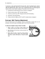
Tracking the L-Sealer Takeaway Conveyor Belt
From time to time or whenever the L-sealer takeaway conveyor belt has been replaced,
it will be necessary to track or align the belt so that it stays in place on the rollers while
moving and delivering the product. The procedure is simple, but can be time-
consuming.
1. Identify the drive roller and the idler roller. The drive roller is the larger roller. The
idler is smaller and has a crown (rounded surface that is higher at the middle and
tapers outward to give the idler a slight “barrel” shape).
2. Place the belt on the rollers in the center and tighten each adjustment screw as
evenly as possible.
3. Adjust the speed potentiometer on the conveyor timer (adjustment screw for
speed pot is at lower left; see illustration below) to increase the conveyor speed.
4. Start the conveyor and observe the belt.
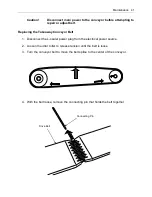
5. If the belt stays centered on the rollers during operation, no further adjustment is
required. If the belt begins to pull towards the front or back, adjust it by turning
the left-hand adjustment screw only. Turn the adjustment screw no more than
one quarter turn at a time
— attempting to make larger adjustments will only
prolong the adjustment effort. Return the conveyor to normal operating speed
when finished.
0
1
2
3
4
5
POWER
OUT
MODE
AT11DN
RUN
A
CONVEYOR
sec.
Speed Pot
Mode Selector
Summary of Contents for Combination EC Series
Page 2: ......
Page 4: ......
Page 73: ...Appendix A Electrical Schematic 73 Electrical Schematic L Sealer ...
Page 81: ......


