

- 58 -
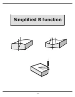
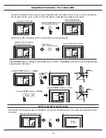
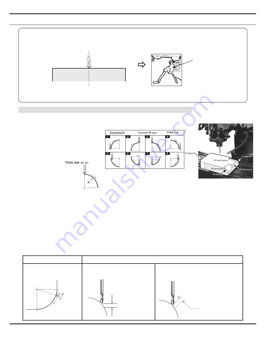
Simplified R Function
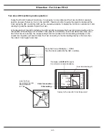
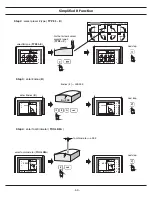
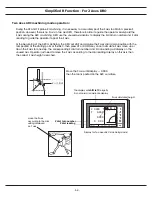
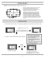
In case 2 Axes ES-12 is used, we must first reset the Z Dial to simulate the initial Z position at the ARC's start point
**** Only for 2 Axes DRO, not valid if a 3 Axes DRO is used ***
** Posit the Tool at start point of the ARC to be machined **
Set the Z axis Dial
to ZERO ( 0.00 )
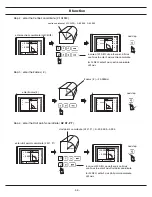
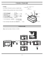
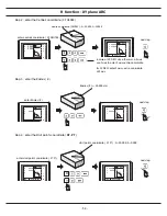
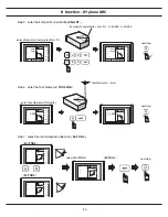
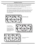
1. Select the work plane - XY, XZ or YZ plane R
2. Select the R type (
R type
) - Type 1 to 8
3 Input R's Radius (
R
)
4. Enter to Tool Diameter
(
TOOL DIA
)
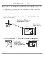
Following parameters needed to enter into the DRO for simplified R machining
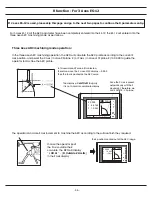
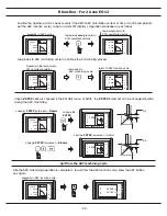
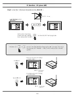
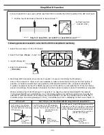
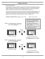
5. Machining STEP increments ( Only when for 2 axes ES-12 is used or machining the XY plane R )
Since in the 2 axes ES-12, there is no Z axis available, in order to make the machining of XZ and YZ plane R
possible, we need to simulate the Z axis position by mathematical method, also, we need to simulate the
Z up/down increments by the UP or DOWN key press so that the DRO can calculate the XZ / YZ arc machining
position accordingly, this parameter is to specify how the Z position increment when UP or DOWN key is pressed.
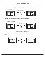
When machining the XZ and YZ plane R in 3 axes ES-12, no need to enter this Machining STEP increments,
it is because the DRO can calculate the X or Y machining positions and set those points to zero to guide the
operator to machine the ARC according to the current Z position. In case the Z position are out of the ARC's
Z position range, an warning message [ r. OU LI] - R is outside the Z limit is displaying on the Z axis of the ES-12.
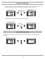
For XY plane R, Max. distance
between interoplated points is
to be specified as the machining
STEP increments
XY
plane
R
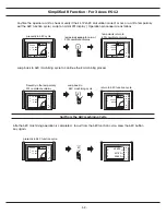
XZ / YZ
plane
R
(
for 2 Axes ES-12 only, not for 3 Axes ES-12
)
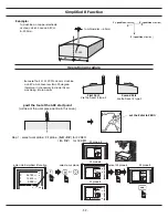
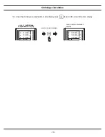
Fixed Z incremets
per UP or DOWN pkey
press
Z STEP =
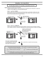
For XZ/YZ plane R, the Z STEP parameter
is the Z step increments per UP or DOWN
key press. The Z increment distance is fixed
and specified by this
parameter.
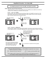
For XZ/YZ plane R, if the R MODE parameter of SETUP
is selected to be MAX CUT, the DRO will calculate the
Z step increments per UP or DOWN key press so that
the Max. distances between each machining step
are approximately the same for a
smoother ARC machining.
max. distance
between
interpolated points
MAX CUT=
MAX CUT=
max. distance
between
interpolated points
Summary of Contents for ES-12
Page 8: ...1 Basic Fucntions Basic Functions BASIC...
Page 15: ...8 Built in Calculator Calculator...
Page 27: ...20 REF datum memory...
Page 31: ...24 LHOLE tool positioning for the Line Holes...
Page 35: ...28 INCL Inclined angle tool positioning...
Page 40: ...33 PCD tool positioning for Pitch Circle Diameter...
Page 45: ...R R R 38 tool positioning for ARC machining...
Page 63: ...R R R 56 Simplified R function...
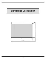
Page 73: ...66 Shrinkage Calculation L L X 1 005...
Page 91: ...Parameter Setup B 1 SET UP...